I have been the road warrior lately if you haven’t noticed a certain decline in the blog posts… One place that seems to keep pulling me back is Randolph, VT, which is about as close to the geographical center of Vermont as one can get and still be on a roadway. There resides the silent FM station formerly known as WCVR, to be returned to the air as WXVR by Vermont Public Radio.

WCVR went on the air in 1982 and was a community-oriented country station for 17 years. Then in 1999, it was sold to Clear Channel and things began to go downhill. Over the next decade, the station transferred ownership four times. Finally ending up with absentee landlord Vox Radio. By the time the station was sold to Vermont Public Radio last May, the years of neglect were compounded and the main transmitter was no longer running. The transmitter site was raided before the transfer and things like spare parts, a backup transmitter, and a dummy load were removed. As one engineer from VPR noted, the only thing of any value is the Shively antenna.
This story probably repeats itself a thousand times throughout the country as a small market, formerly community radio stations are left to die on the vine by big-time corporate radio gurus in Atlanta, San Antonio, and Las Vegas.
Said station has a McMartin BF5-K transmitter that is not currently running and by the accumulations of dirt, debris, and other evidence, has not run in quite some time.
The beauty of a McMartin FM transmitter is it is a grounded grid. Can’t get much simpler than that when it comes to FM transmitters. The downside is, of course, McMartin has been out of business for almost thirty years. Thankfully, Goodrich Enterprises is still around and still supports them.
The first order of business was cleaning out the filthy, and I mean absolutely filthy building. Several hours with a broom, dustpan, and shop vac got rid of most of the dirt and made my skin less likely to crawl. Then came the fateful attempt to run the transmitter. Loud arcs, power supply hum, and dimming lights revealed that all was not well. All of the fluorescent lights were out, new bulbs did not fix the problem. So, to the Grainger to pick up new fixtures and install them. Now, at least, we could see what were doing.
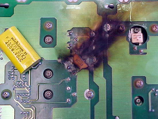
Next, step-by-step troubleshooting of the High Voltage power supply. Step one, resistance checks on the HV transformer and filter chokes to the ground. Next forward and reverse resistance checks on the rectifier stacks. All of those looked good. Next, we isolated the HV transformer and the rectifiers and turned the transmitter on; no problems. Next, we added the metering and filtering capacitors and turned the transmitter on; no problem. Finally, we found the problem with the HV power supply RF filter on the side of the PA enclosure. In a McMartin FM transmitter, there is a little box mounted on the outside of the PA enclosure that holds half the parts in this circuit. Taking that box off revealed a bad 200 pf 7.5 KV doorknob capacitor that was shorting to ground. Lots of arc marks, soot, debris, and other stuff make me think that this problem had been going on for a long time. I can kick myself for not taking a picture.
Hopefully, this thing will run for a few months while a replacement is sought.
Compounding that issue is the leaking transmission line connector at the bottom of the antenna, which was fixed, but there appears to be another leak somewhere else as the line still does not hold pressure for very long.
VPR is going to broadcast their Classical Music format on this station, starting as soon as we can make the transmitter run.
UPDATE: Pictures:
Transmitter building:
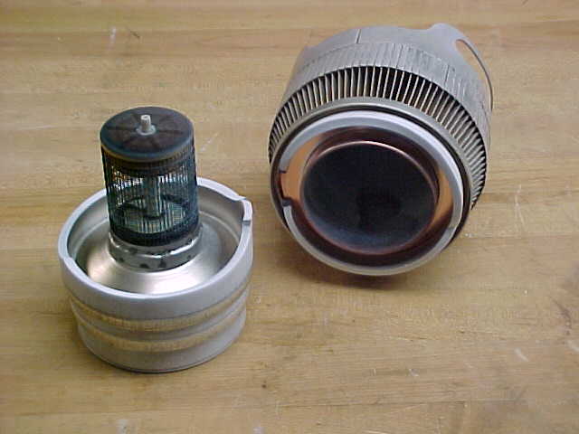
WCVR Mc Martin BF-5K transmitter:
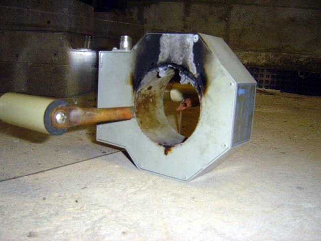
Arcing power supply filter section, the bad door knob capacitor has been replaced, still evident are the arc marks on the PA cavity:

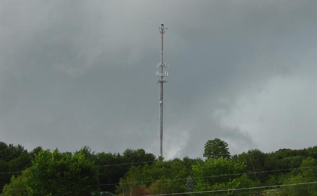
Mc Martin BF-5K transmitter on the air:

We’ll see how long that lasts.