A story about skirted AM towers and Cellular carriers.
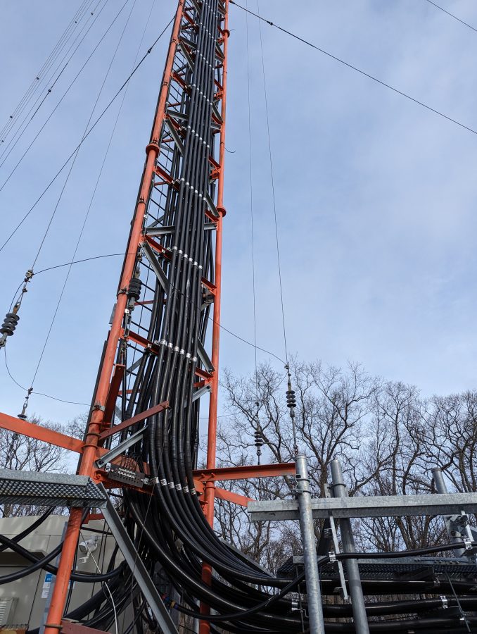
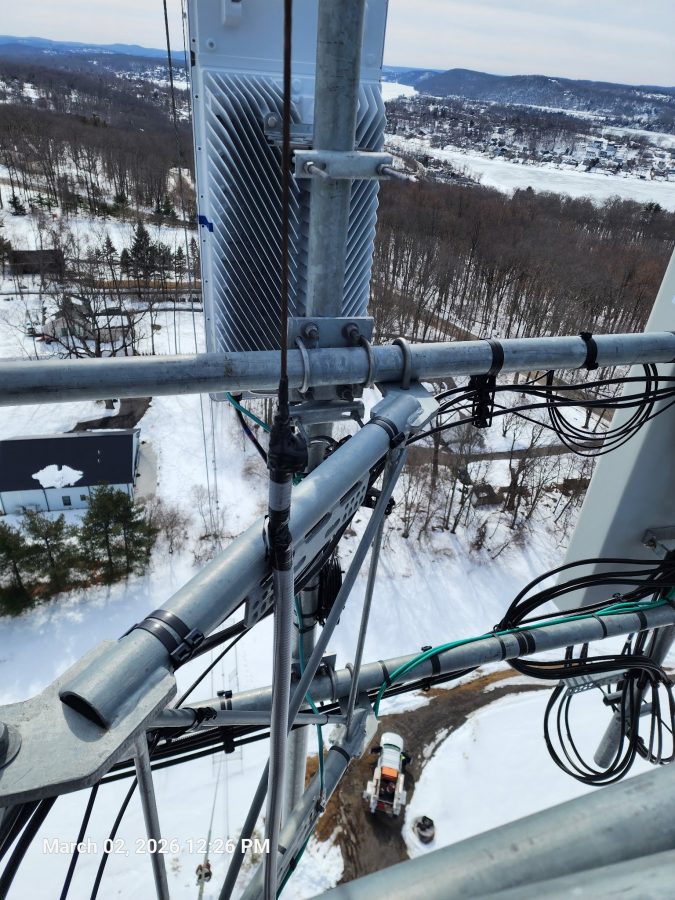
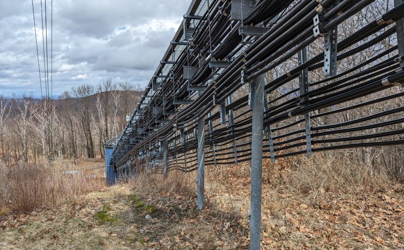
Skirted AM tower with cellular equipment
We take care of a few sites that have skirted AM towers with Cellular equipment installed. For the first few years, all was well. The cell carriers put up their equipment under supervision and we made sure that the AM station’s antenna still was working when the were finished. At some point, things changed.
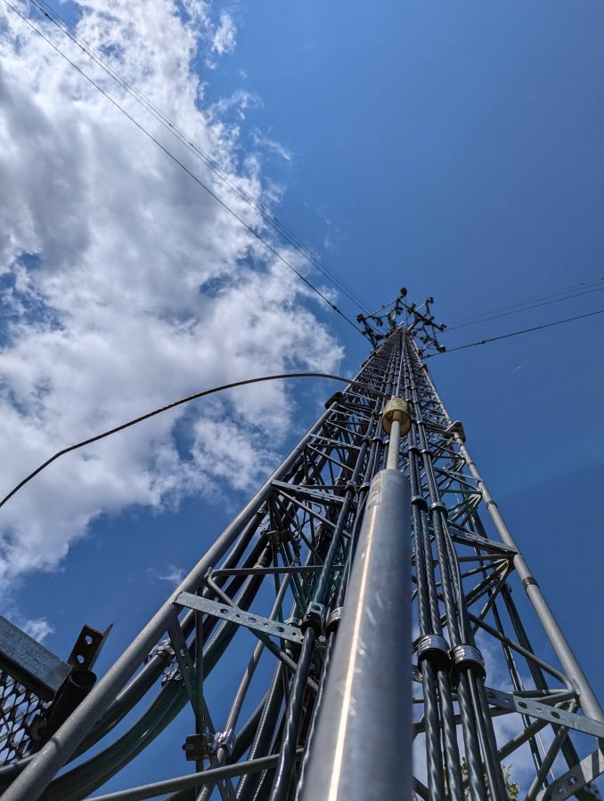
Stiff arm hitting skirt wire
It is a little bit hard to see because the camera is focused on the foreground and not the background, but the stiff arm from the cell carrier sector is shorting the skirt wire to the tower.
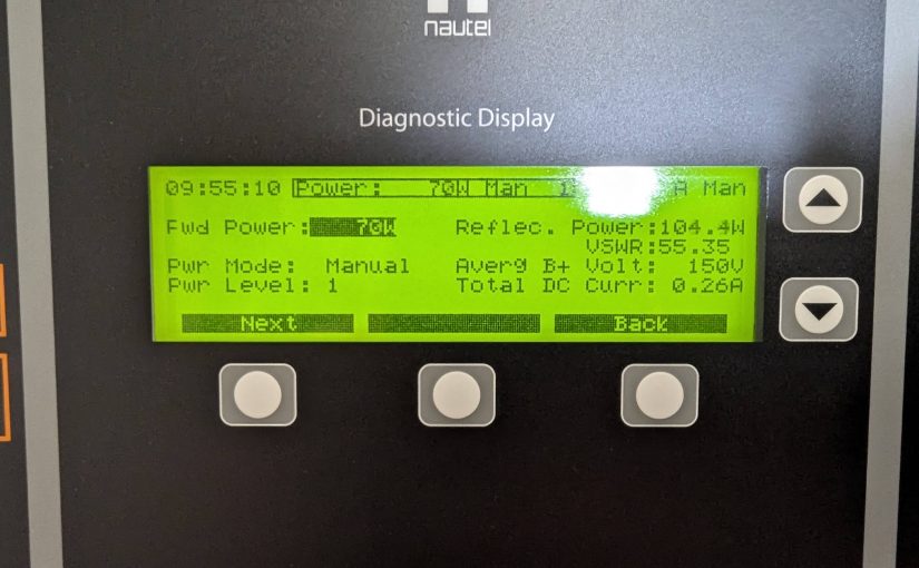
More often then not these days, tower crews show up unannounced and start working on the tower. I had a call from a client their station being off the air only to arrive on site and find a crew on the tower with the AM skirt grounded by a set of battery jumper cables. The ground crew said they kept getting shocked by the wire so they grounded it.
In other cases, they show up, do the work and leave before anybody notices. Then, at some point somebody checks the AM transmitter readings and sees a problem.
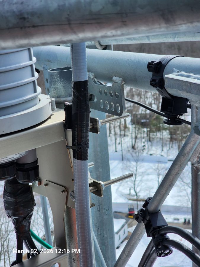
AM skirt wire, shorting against mounting bracket
In another situation, the tower crew came and installed new equipment. They installed an insulating sleeve around the skirt wire (while the transmitter was on) but did not secure it well enough. The eventually, sleeve slipped down the wire and it shorted. No one, not even the tower owner, knew about the tower crew being on the tower.
AM skirt wire insulating sleeve
Same tower, the sleeve on this wire rotated around so that the opening was facing the stiff arm causing a large charred, melted plastic area.
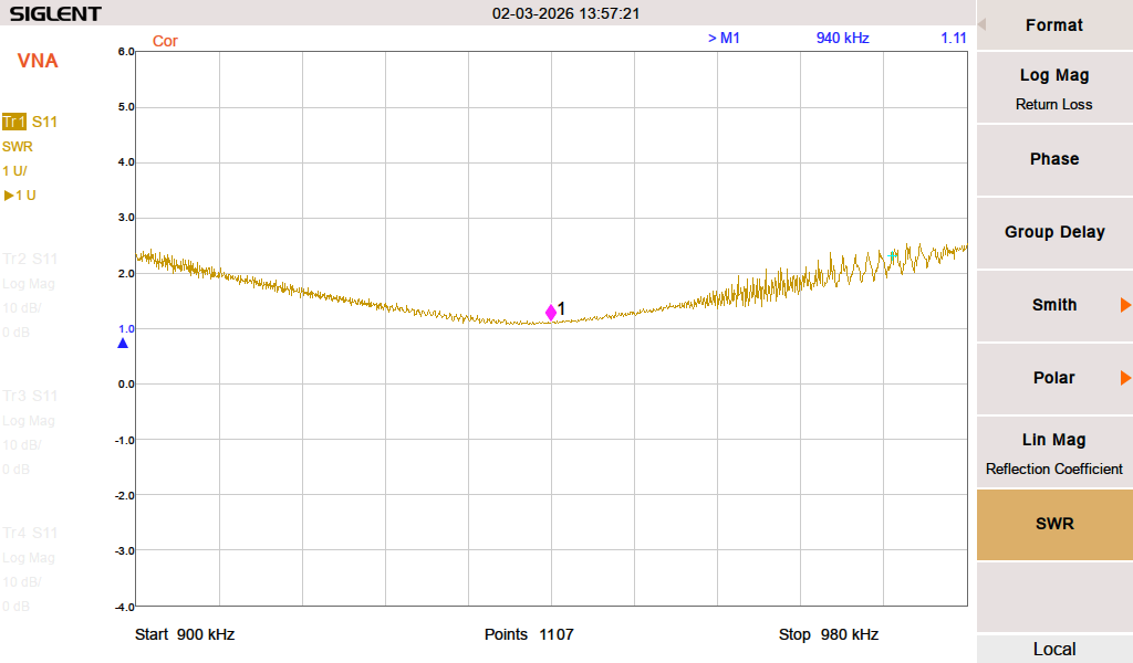
These were repaired with some left over coax-seal and electrical tape. After this, I was able to retune the ATU using my network analyzer.
The only solution, it seems, is to put up more cameras with motion detection notification so when somebody shows up unannounced the station will at least know about it.
The ability to do a Distance to Fault Measurement can greatly speed up the troubleshooting of potential antenna and/or transmission line problems. DTF measurements take on one of two forms; Time Domain Reflectometry (TDR) and Frequency Domain Reflectrometry (FDR).
TDR is the traditional method of measuring Distance to Fault. The test equipment sends short DC pulses down the cable and measures any return loss or SWR. Energy reflected back toward the instrument will plotted based on the time difference between the transmitted signal and the received reflection, similar to RADAR. This works well finding opens or shorts, but may not see lesser faults that could still be causing problems.
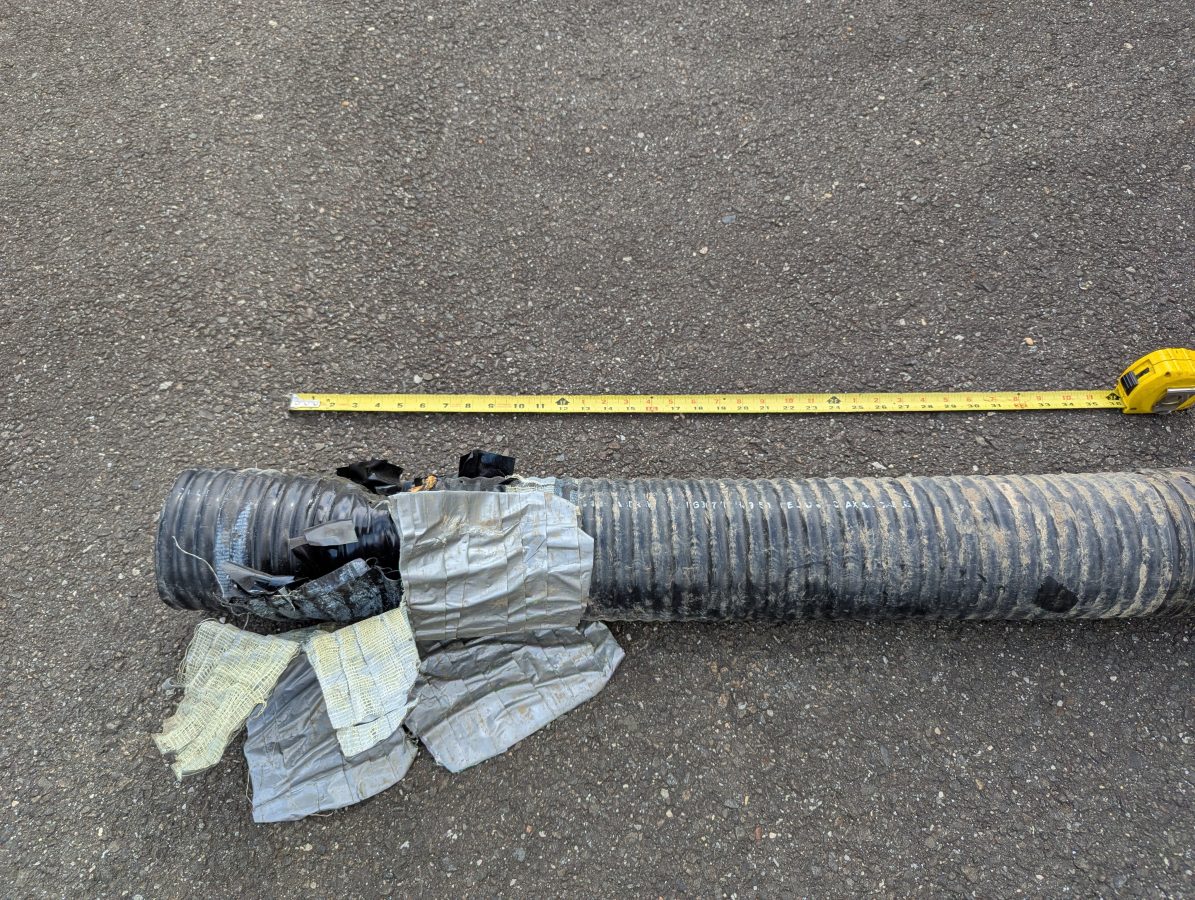
Damaged six inch coax
FDR is now common in most field models of Vector Network Analyzers. An FDR sends a frequency sweep down the cable then uses an Inverse Fast Fourier Transform (FFT) function to convert the information into a time domain. FDR can more reliably detect smaller issues with cables such as kinks, sharp bends, water in the cable, poorly applied connectors, or bullet holes. The piece of dented cable above would not have given a large reflection on a TDR, but on an FDR it would show up very nicely.
Like a VNA, an FDR needs to be calibrated for the sweep frequencies in use. The frequency span or bandwidth of an FDR has a major role in DTF measurements. A wider span will result in more precise fault information, however, it will reduce the over all length that the instrument can test. For most broadcast RF applications, cable lengths are less than 670 meters (2200 feet). Many instruments will adjust the maximum distance automatically based on the chosen span and velocity factor.
For my equipment, a Siglent SVA 1032X, the maximum distance for any frequency span can be found with this formula:
Maximum Distance (meters) = 7.86 x 10⁴ x Velocity Factor/Span (MHz)
Thus, to get best resolution sweeping a cable that is 670 meters long with a velocity factor of 86%: 7.68 x 10,000 x .86 / 95 MHz = 695 Meters maximum distance.
The resolution for any frequency span can be calculated with the following formula:
In this case, the resolution would be +/- 1.35 meters. For shorter cable lengths a larger span can be used for better resolution.
My preference is to center the sweep frequency around the channel or frequency of the system under test.
To use a DTF function, a few inputs are needed:
The velocity factor of the transmission line
Cable attenuation for the swept frequency in dB/Meter
The approximate length of the line under test
The cable velocity factor and attenuation can be obtained from the manufacturer’s data sheet. Keep in mind that the manufacturer’s data is an estimation. These are usually pretty close to the actual number, but may vary due to tight bends in the cable, any splices, transitions to different cable, etc.
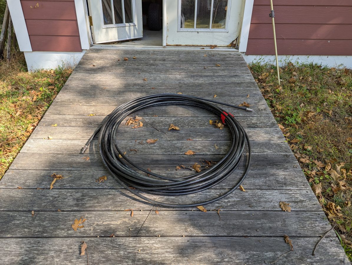
Cable to test
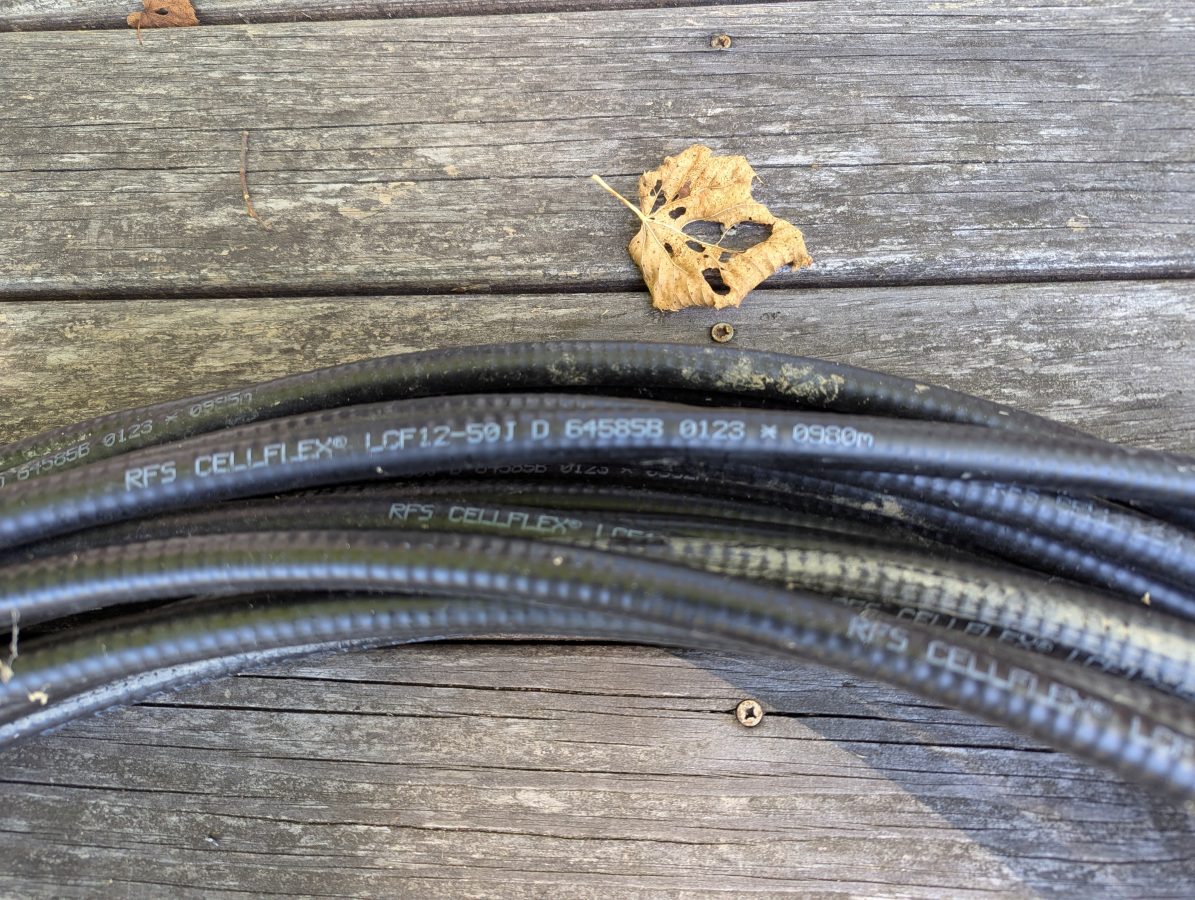
I had this used 1/2 inch RFS LCF12 50J cable in the barn, left over from project. Fortunately this is newer cable and it had the length marked out in meters. The beginning number was 0980 meters, the end was 1021 meters. Each meter marking has an asterisk before the number. I used a meter stick to measure out the distance between the asterisks and they are exactly one meter apart. I then measured the distance between the asterisk and the connector on each and ended up with 1.49 meters (4.9 feet) additional length, making the total length 42.49 meters (139.4 feet). The manufacture’s specification on velocity factor is 0.87 or 87% of the speed of light.
Manufacture’s markings
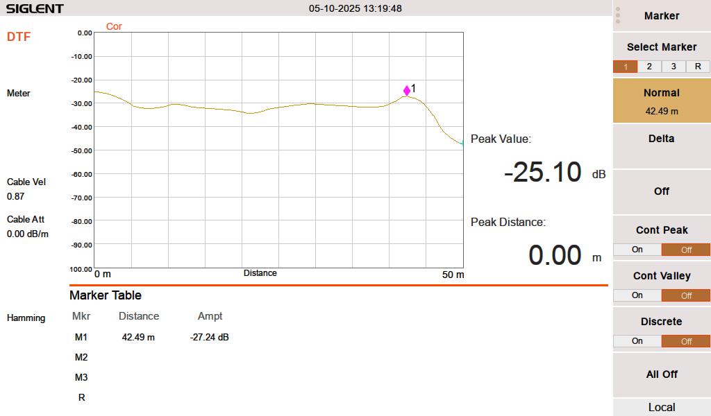
When I test this line with a 50 termination, it looks like this:
FDR DTF, 50 ohm termination at 42.49 meters
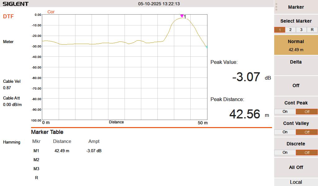
When I test the line either open or shorted, it looks like this:
FDR DTF, cable shorted at 42.49 meters
I swept the cable at HF frequencies (3-30 MHz) since I think that is what this is going to be used for. At 3 MHz, the cable has a loss of approximately 0.003 dB per meter, which is inconsequential for this test. The velocity factor of 0.87 is pretty close. A longer run might indicate that it is actually 0.875 or 0.88.
Velocity factor and cable impedance are very important when using the Moment of Methods (MOM) system for AM antenna work. In that situation, both need to be obtained with a VNA for the FCC application.
The best practice is to sweep into a terminated line. In an AM system, a termination can most often be applied at the ATU input J plug. Sweeping into an antenna is possible, however there are several things that may lead to poor results. Most often, an FM antenna will look like a short on a DTF measurement. A UHF slot antenna will look open. In addition to that, the DTF measurement may be corrupted by any signals being received by the antenna while the system is under test.
Update: This was delivered on May 2, 2025 in good condition. It took 24 days to get here, 21 of which were sitting in Memphis. Also, it works great!
A cautionary tale.
I have purchased and sold several things through Ebay over the years. Most of the time the transactions go smoothly. The item is more or less as described and it arrives in a reasonable time period.
All good.
Recently, I saw this very nice looking Agilent E5061B Vector Network Analyzer. The price was right and it even came with this nice hard case. This is great, I need something like this for an upcoming project.
The only very small, almost too small to notice possible issue was; its in Canada. With all the trade rhetoric going around, I thought, perhaps I should look to buy something from the US. Nah, its fine, after all, it is not coming from China.
Nope.
The order went in, the seller shipped the package, it arrived in Memphis, TN and the trail goes cold after that:
I have emailed and called FedEx several times. They say, “all good, we have all the documentation we need, it will be shipped out shortly.” Last time I called, I spoke to a woman in the Philippines who’s phone cut out with every other word.
It seems probable that all international shipments are stuck in some giant FedEx terminal waiting for someone to say okay or calculate some tariff. The pessimistic view is that it has been stolen. I have lost things in transit.
I should have listened to my little voice. While the problem is not with Ebay itself, importing equipment from another country is problematic. I would advise anyone bidding on Ebay to pay close attention to the location of the item you are purchasing.
In the mean time, I still need to finish my project…
This Broadcast Electronics FM3.5A is 40 years old. There was a small problem that took the station off the air for a couple of hours this morning. The high voltage shorting solenoid fell apart, causing the 40 amp breaker in the service panel to trip.
BE FM3.5A defective shorting solenoid
These types of failures will become more frequent as the transmitter ages. Things like air switches, blower motors, tuning and loading mechanical assemblies, circuit breaker fatigue, plate rectifiers, screen and plate bypass capacitors, exciter and controller fans, etc. The list of potential failure points can get quite long. The fact is, nothing lasts forever.
Manufacturers nameplate
There is no backup transmitter for this site and there is no easy way to get a temporary unit on line, if needed. This is not the oldest main transmitter that we service with no backup. That honor goes to a CCA DS-3000 built in 1970.
The question is; how long should old tube transmitters be kept in service? Also; how long should we (an independent service company) agree to maintain them? The temporary solution for the above failure was to remove the broken shorting bar and turn the transmitter back on.
Broken shorting bar removed
That creates a safety issue for anyone who may need to work on the transmitter before the replacement arrives. It also creates a potential liability issue for my company.
I put a big label on the back door indicating that anyone doing service needs to discharge the power supply capacitor with the grounding stick (which they should be doing anyway). But I will feel better when the shorting solenoid is working again.