Whilst working in the generator room at WFLY, I found this bit of treasure stashed on an overhead shelf:
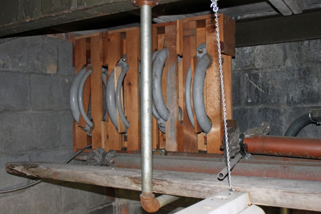
General Electric BY-4-C FM circular broadcast antenna, ca 1948
That is a very old FM broadcast antenna from 1947-48. It must have been intended as a spare antenna in case the main antenna had a problem. It was never needed, so it remains in its original shipping crate. I would think that these were rather well made since the original main antenna was in service from 1948 until 1970 or so when it was replaced with a Shively 6710.
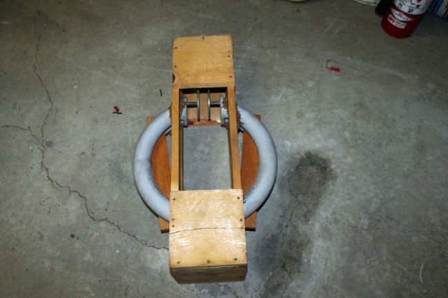
General Electric BY-4-C antenna element
The entire antenna is intact including the Interbay lines, power divider T’s, and tuning section. Of course, it is of little use to the radio station today, as it is horizontally polarized. Perhaps some museum somewhere? I don’t know, it would be kind of neat to put it all together and use it as an exhibit.
Update and bump: I hate to rehash old stuff, but I added quite a bit of information to this post, including .pdfs of all the Barbeau letters, blue prints, etc. I’ve been doing quite a bit of work at this site lately, so it is in the front of my mind. I have also been reading about the Rural Radio Network, which covered western and central New York.
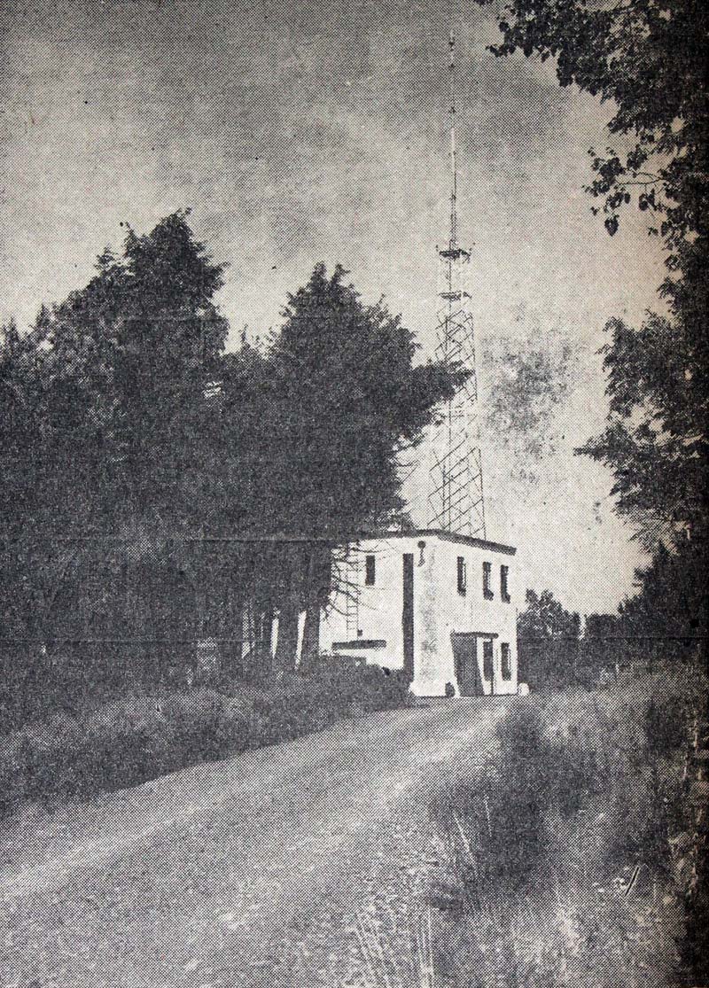
WFLY transmitter site, August 1949
Several years ago, I rescued an old filing cabinet that was being trashed. This particular file cabinet was moved to a transmitter site during the great radio consolidation of the late 90s and early 00s. In it, I discovered a treasure trove of early documents about two radio stations from the Albany NY area. I thought it would be interesting to document the building of one of the early FM stations in Albany, WFLY.
Albany is the capital of New York. There were several early (prior to 1940) AM radio stations in the Albany area:
WGY previously owned by General Electric in Schenectady, signed on in 1922
General Electric, who worked closely with RCA in radio development and experimentation, was working on TV in 1928 and FM radio in 1938/39. There were also several early (prior to 1950) FM stations in the area:
GE owned W2XOY on 48.5 MHz (circa 1939), later W85A, WGFM, and WRVE 99.5 MHz.
Independently owned W47A on 44.7 MHz (circa 1940), later WBCA 101.1 MHz, now gone.
WTRY owned WTRI-FM on 102.7 MHz (circa 1947), off air by 1954. 102.7 frequency later used by WEQX in Manchester, VT
These stations operated from transmitter sites in the Helderberg escarpment on land that was formerly owned by the Albany Bible Institute. It is interesting to note that two of the four FM stations did not make it past 1955. In 1967, WTRY did make a second attempt at FM, launching WDKC on 106.5 MHz, which is today known as WPYX.
It would appear the Troy Record initially applied for an FM broadcasting license in late 1946. The paper trail that I found started in early 1947 when the station hired consulting engineer Ernest Barbeau of Schenectady to oversee the construction process for the studios and transmitter site. Ernest Barbeau, in an introductory letter to Frank York, publisher of the Troy Record, notes himself as a former GE engineer and assistant to W.R.G. Baker, General Electric’s television pioneer. At the time, it was already understood that height means almost everything in FM broadcasting. There are several letters dealing with land acquisition and transmitter building construction.
Below is a chart of all the various Barbeau letters written in 1947. I have scanned and uploaded .pdf files of each letter, sorted by date (the entire archive is available here (6.5 Mb .zip)):
This is a treasure trove of information on how this, and perhaps other early FM and TV stations went about finding land and building remote transmitter sites. Remember that before this, AM transmitters could be placed in any convenient location with enough space for the tower and ground system. The line-of-sight nature of VHF required high locations, which in the Northeastern US, means prominent hills or mountains. Sadly, this paper trail goes away in 1948.
Here are some of the highlights found in the letters above:
Washington DC consulting engineer for the project is John Barrons, who at one point suggested a different transmitter location closer to the city of Troy. Barbeau insists that the Helderberg location is best because the GE engineers chose it for their FM and TV experiments.
Negotiations with several land owners along the edge of the Helderberg escarpment are finally successful, with a 10-acre parcel of land purchased from Mr. La Grange, noted as being across Camp Pinnacle Road to the south of the WBCA transmitter and adjacent to the west of the GE parcel, cost $2,000. From this, I surmise the former W47A/WBCA site stood where the former WHMT/WVCR site stands today.
Land survey completed by Mr. J. Kempf of Albany.
The FCC application is completed with a new transmitter location, antenna height, and frequency of 92.5 MHz (this was changed to 92.3 MHz prior to sign on).
At one point, Barbeau tried to hire Walter Watson, an RPI architecture student, to draw up the studio floor plan, paying him $15.00. At first, Watson agrees, then backs out of the deal. Frank York hires an architect to draw the studio floor plan and the transmitter site-building plan.
Once the plot of land for the transmitter site is purchased, several different building locations and antenna configurations are discussed. It is noted that both WBCA’s and WGFM’s original antenna was mounted on a pole at ground level. The later station was moved to a makeshift tower.
WBCA management raises concerns with the FCC about potential interference from the new station’s transmitter and potential STL, noted as an S-T link.
In September of 1947, Frank York expresses some concern with the viability of the project, Barbeau sends several “pep talk” letters saying that FM radio is the future of broadcasting.
The building site is chosen, land cleared, access road installed, work done by Orsini Brothers Construction from Altamont, clearing and road work cost $2,000.
The call letters WFLY are chosen, they are the initials of Frank Lloyd York.
An 80-foot Blaw-Knox self-supporting tower is purchased and installed by Zane Construction, cost of the tower is $1,700 installation was another $200.00.
The well is drilled by Stewart Brothers well drilling from Guilderland, cost of $5.90 per foot drilled, total cost unknown.
Transmitter building work began, the building is noted as a two-story, concrete block construction, work done by Orsini Brothers.
A GE BY-4-C four-bay circularly horizontally polarized antenna and a 3 1/2-inch Andrew transmission line are installed on the tower.
Building construction progresses, and telephone and electric services are installed. Three-phase electrical service cost $2,100 from New York Power and Light.
The studio site was chosen at the Troy Hotel in downtown Troy.
Living quarters were constructed on the second floor of the building for full-time transmitter engineers.
A GE BF-3A 3 KW FM transmitter was purchased and shipped.
Building construction completed.
The transmitter was installed and tested.
Telephone circuits between new studio installed and tested.
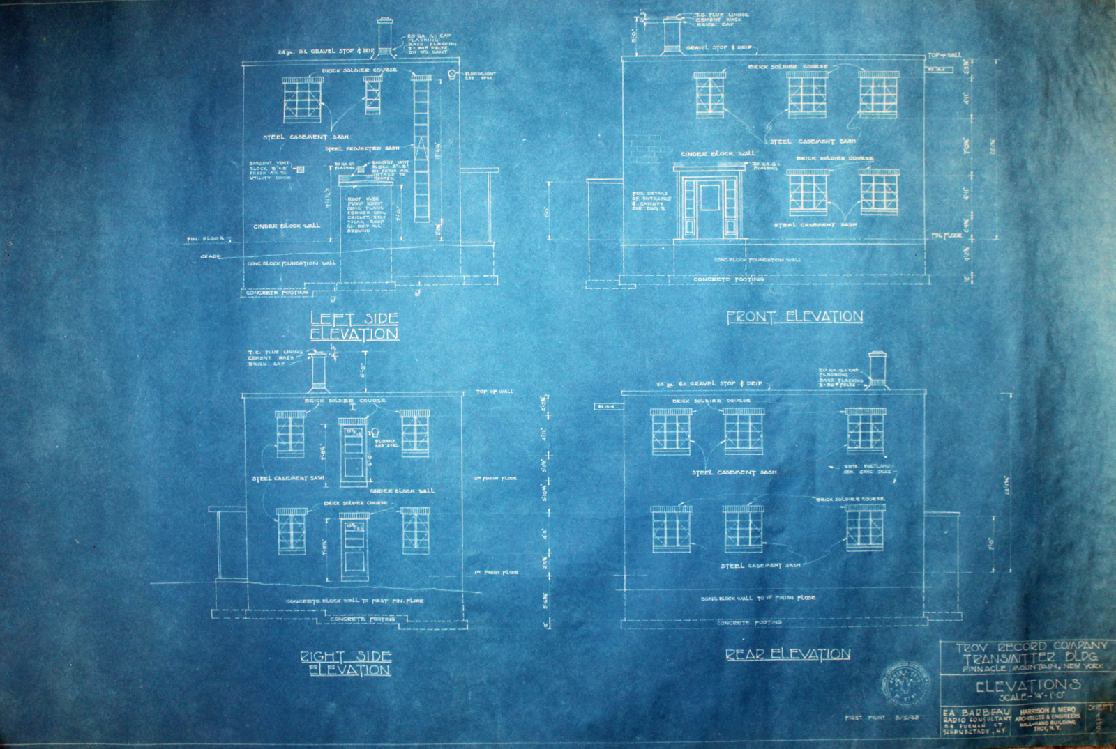
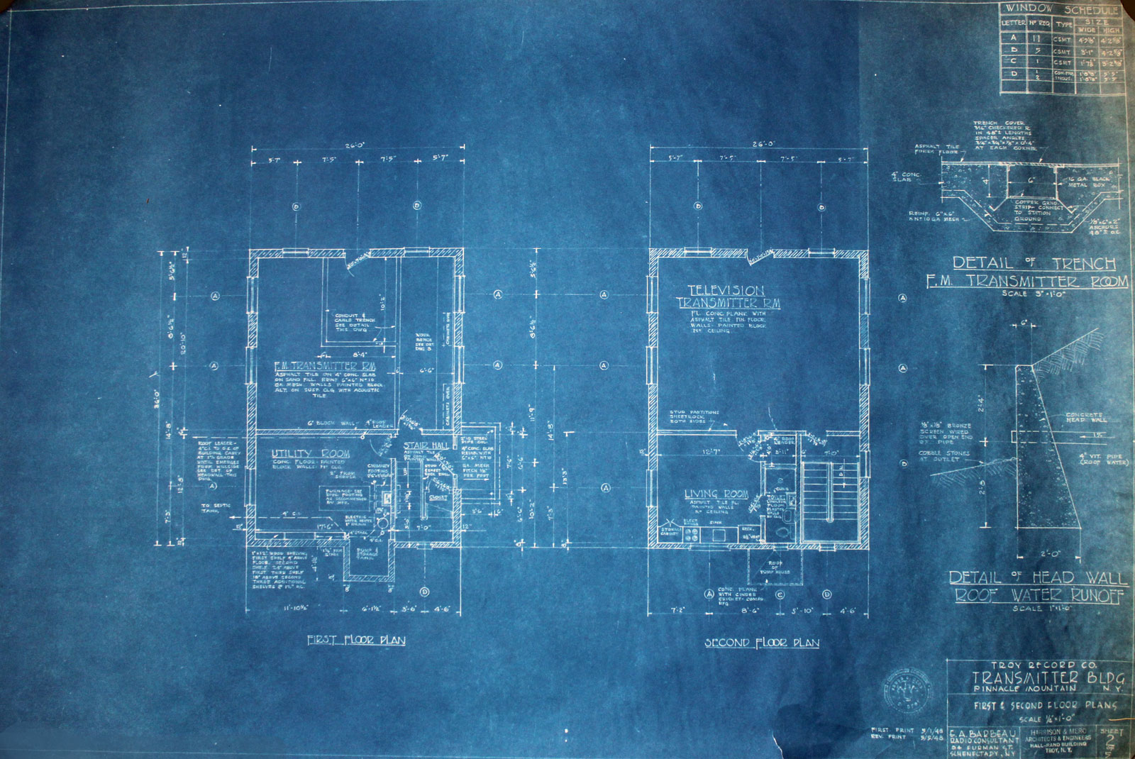
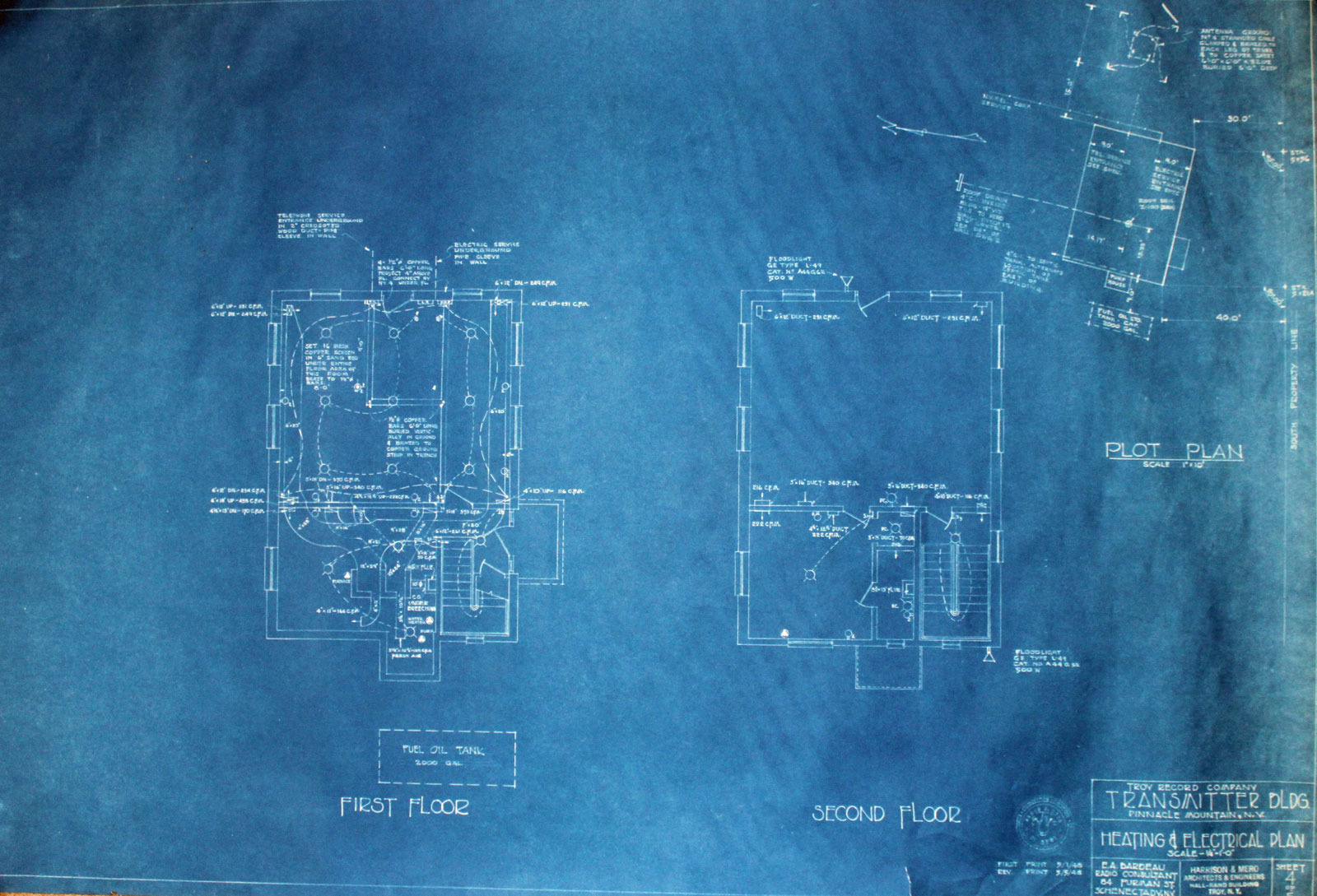
WFLY transmitter site building elevationsWFLY transmitter building floor planWFLY electrical drawing showing grounding and tower
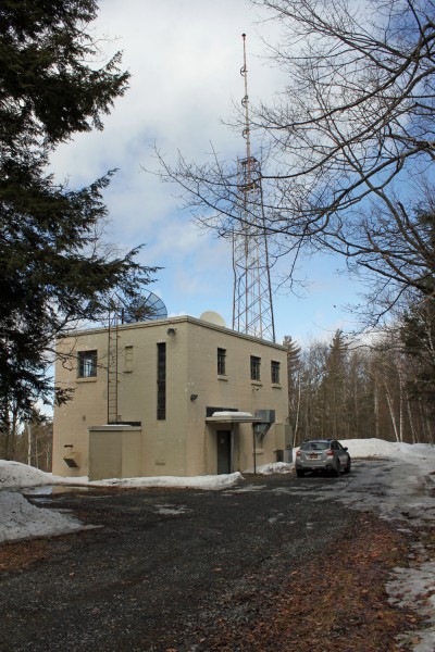
The transmitter site construction was finished in the spring of 1948. The studios were completed in late July of 1948 and the station signed on the air on August 18, 1948. This is the transmitter site that they ended up with. as it looks in 2015:
WFLY transmitter building, New Scotland, NY
In addition to the construction, there was quite a bit of difficulty from the WBCA management, who were concerned about possible interference. WBCA was part of the “Continental Network” and received most of its network programming via direct over-the-air relay from W2XMN/W31NY, 43.1 MHz, in Alpine, NJ. They complained to the FCC about potential interference on both their over-air network relay (43.1 MHz) and the Studio to Transmitter Link from downtown Schenectady on 950 MHz. In the end, the FCC was unimpressed with these arguments and granted WFLY its operating license.
The transmitter building was made twice as large as needed because the Record had plans to launch a TV station and possibly a radio facsimile service. In addition to this, there were complete living quarters on the second floor which included a bathroom, shower, kitchen, bedroom, and large living room area. This was in the era before remote controlling of transmitters was permitted by the FCC. It took a hardy soul to live at the remote transmitter site full-time. Even today, it is far outside of town and can be difficult to get to in the wintertime
These mountain-top transmitter sites did not exist prior to the advent of TV and FM. The amount of planning and work that went into launching this station is quite impressive. For the early FM radio stations, this type of effort and expense was probably typical.
It seems branding and programming issues are a long-running problem for radio stations. This is a copy of something that was made at WALL in 1974. It has been circulated extensively in the NY metro market, but perhaps some of you from other areas or countries have not heard of it yet. There is no WVWA 900 in Pound Ridge, it is a fictitious station:
What is hilarious is that the same exact this is still going on forty years later. How many times have programming consultants, program directors, and corporate programming gurus sat around and said “What we really need is a catchy name, like The Buzz or something.” I don’t know how many times I have heard “The X” or “The Eagle” or “fill in stupid name here.” Do the listeners really think “Oh wow, they changed their name, I will listen to this station now!” No, not likely.
The funniest part is; “After more than 100 hours of extensive research… (the programming consultant) developed, refined, molded, polished, honed, shaped and pulled out of left field a revolutions new formatic programing concept…” Play music, say nothing, and scream “NINE!” between each song.
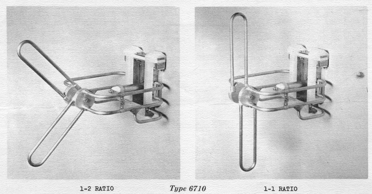
Perhaps that is one Shively Antenna that you haven’t heard of. They were an oddball combination of a horizontally polarized antenna with an adjustable vertical element. This design allowed the station to adjust the ratio of horizontal to vertical power from a range of 1:1 to about 4:1 (H:V). Why would this be a desirable feature?
Back in the early days of FM broadcasting, almost all stations had horizontally polarized antennas. This system worked remarkably well, stations could broadcast at moderate power levels over fairly long, line-of-sight (or mostly line-of-sight) paths. Most FM receivers were stationary units installed in people’s homes often with outdoor antennas.
It was not until the late 1960s and early 1970s that FM radio receivers became a stock option in most low and mid-cost automobiles. It was then that a slight problem with FM broadcasting was discovered; car antennas are vertically polarized. People driving around in their new machines found that the FM reception was not all that great. Stations began adding a vertical component to their signal to help improve the mobile reception situation.
I found this Shively Brochure in a file cabinet drawer at the WFLY transmitter site. This model antenna was ordered and installed by that station in 1970. It had a 3:1 horizontal-to-vertical ratio. Why not install a fully circularly polarized antenna? Because often that necessitated installing a new, more powerful transmitter. Every watt of power taken from the horizontal plane and added to the vertical plane reduced the ERP by that much and had to be made up with more transmitter power output. Oftentimes, the ratio of H:V power would be adjusted to take up whatever headroom there was in the transmitter and the station would run that way until the next transmitter replacement cycle.
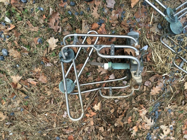
I found the remains of this antenna in the woods, northeast of the tower.
Shively 6710 antenna section
This section looks pretty well destroyed. It is probably better to dispose of these types of things by scraping, them rather than dumping them in the woods. While there is not a lot of scrap value to this unit, it can become attractive nuisance to copper thieves and other vandals if it is left laying about.
It is a strange-looking piece of kit, a sort of make-do until the situation could be fully rectified. I think this antenna was in service until 1986 or 87 when it was replaced with a circularly polarized ERI.