Short, but interesting video tour of an FM transmitter site in Germany. The analog transmitters are 10 KW Telefunken solid-state units, 5 main transmitters, and two reserve units into an antenna combiner. At approximately the 35-second mark, the video shows a Rhode & Schartz DAB transmitter. Germany uses DAB+ in band III (174-240 MHz).
It is always interesting to see how others are broadcasting.
One of the issues that I have seen at many transmitter sites is inadequate cooling. Time was, when mostly tube transmitters were in use, a simple fan connected to a thermostat was all that was used to cool most transmitter sites. Even then, however, that setup was lacking for several reasons.
Those reasons are:
The amount of cooling provided was limited by the amount of heat in the outside air. On cool winter days, this is not a problem, but on hot, sticky summer days it could be.
No removal of humidity from the transmitter room was possible. This often leads to excess oxidation, corrosion of metal parts, and so on.
No matter how much filtering was used, bugs, dirt, and other debris were sucked into the fan, making transmitter room cleaning a chore.
With solid-state transmitters, air conditioning is required. Solid-state transmitter devices are far less rugged than tubes when it comes to heat. In a high-heat situation, a tube transmitter will keep running until its control circuits malfunction, or it catches on fire. A solid-state transmitter will crash long before either of those things happen.
Air conditioners should be adequately sized for the heat load plus a little extra. That information can be found in a previous post: A tale of two air conditioners.
As we all know, equipment malfunctions. When an air conditioning system goes bad at a transmitter site, things start to happen fast if there is no backup. That is when a backup cooling fan can save the day. A good rule of thumb for sizing a cooling fan is to exchange the total volume of the transmitter room every two minutes accounting for resistance from louvers and intake openings.
3200 CFM cooling fan, WHUD transmitter site
This fan is connected to a 120-volt contact on a thermostat attached to the ceiling of the transmitter room. The thermostat is set to 90 degrees, which gives a good bit of headroom for the air conditioners to maintain the room temperature while turning the fan on before the room gets too hot. It is also important to monitor the room temperature via remote control. Having an alarm contact connected to the fan thermostat is also a good idea.
There is no such thing as too much backup. Installing a louvered cooling fan affords a little bit of extra insurance.
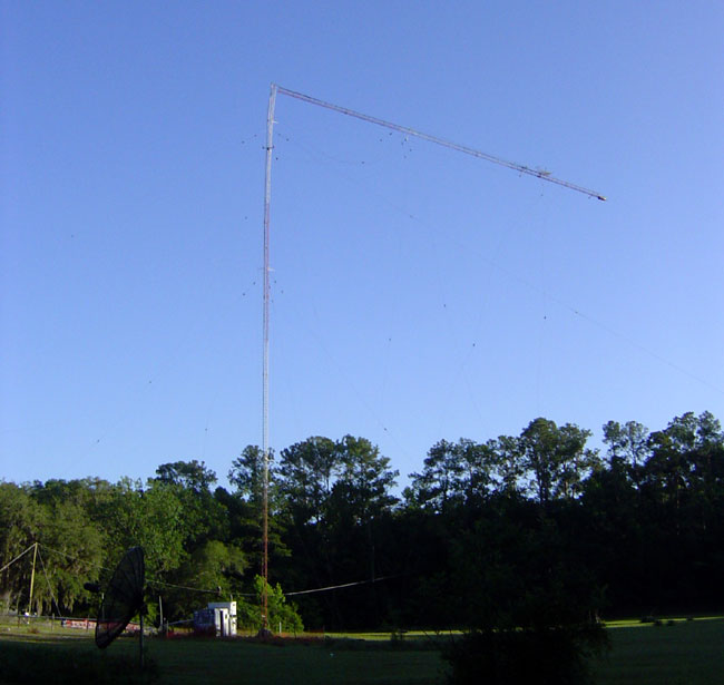
A few years ago, I was involved in removing and rebuilding an AM radio station tower in Gainesville, Florida. The old tower was a hollow leg tower that was rusting from the inside out. It was installed around 1960 or so, but the actual records were sketchy, as the original studio building burned down in 1984. In 2005, the tower climbers came out to relamp it and refused to climb it because one of the legs was rusted through. Therefore, a replacement tower was ordered and delivered.
Prior to starting work, a temporary wire antenna was constructed. Since there were two radio stations diplexed to this tower, it became a bit of a chore to get both signals (980 and 1430 kHz) tuned into the same temporary antenna. In the end, the components available could not create a good load for the 1430 station, so a separate temporary wire antenna was erected for that station. Both stations ran at 1 KW into their respective antennas until the new tower was finished.
WDVH, 980 Gainesville, FL. Top of tower coming down
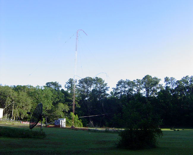
Top section of a 240-foot guyed tower on its way to the ground. This tower had an inner and outer set of guy anchor points. The top section came down after the last guy wire on the outer anchor was cut.
Remains of WDVH tower
Truncated tower.
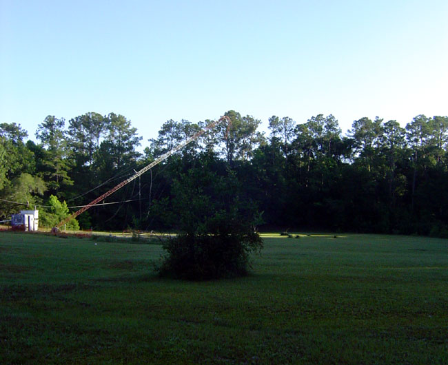
Last section of WDVH tower falling
Bottom section of tower on its way to the ground.
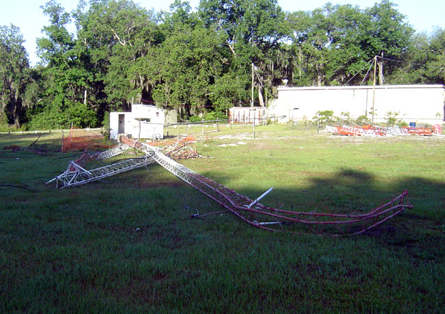
Old WDVH tower on the ground
Tower on the ground. In keeping with the theories on tower failures, this tower fell within about 1/3 its height. The wire antenna supports and the new tower sections can be seen in the background. It took the tower company about a week to stack the new tower. This was done in July, therefore the average daytime temperature was about 100° F (37° C) with frequent afternoon thunderstorms.
I found that question while perusing my search engine statistics today. The short answer in theory is yes. If you are a copper thief, it will most likely look like this:
That being the case, however, it is much more likely that an RF burn will result if one comes in contact with an energized antenna or transmission line. Even small RF burns are painful, large ones can be nasty things. RF burns occur because of the skin effect, that is to say, the higher the frequency of the AC waveform, the closer to the surface of any given conductor the current will flow. It is the reason why five-watt STL transmitters on 950 MHz use 7/8 or 1 5/8 inch cable to reduce losses.
When a human body part comes in contact with an energized RF antenna, the body part becomes part of the circuit, thus it follows the same principles. The extremity that is making contact will have its skin burned off. It also smells bad.
Getting an RF burn is a painful lesson on what not to come in contact with around a transmitter site. But, that is not all. Simply being in close proximity to radiating elements of antennas will induce body tissue heating, just like a microwave oven. This can lead to all sorts of short-term and long-term damage to organs and other problems.
Therefore, the best thing is to avoid radio and cellular towers if you do not know what you are doing. Stay out of fenced-in areas around tower bases. No matter how tempting that copper may look, you could be seriously injured or killed if you cut the wrong thing.