NOAA All Hazards Radio has been around since 1960. I have a Midland Weather Radio receiver in my house because we live in a rural area. We certainly do have weather events; Severe Thunderstorms being the most common. We have also had Tornados, Floods, Hurricanes, Winter Storms and Blizzards. It is useful to have, especially when the cell phone and/or public network go down.
That system operates on the same frequencies and manner as the NOAA All Hazards Radio system.
It appears that the Canadian government is discontinuing service as of March 16, 2026 and replacing it with an app. That seems short sighted to me; I don’t know how many users of Weather Radio Canada there are, but I’d bet there are quite a few. It also assumes that everyone in Canada has a smart phone. Given the economy and the expense of a new iPhone (or Android), I think this is far from the case.
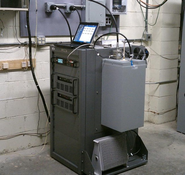
Nautel NG1000 NOAA transmitter
I did get thinking about what would happen here if the NOAA system went away. Could the Emergency Alert System still get reliable local alerts out over the air? I know that most of the radio and TV stations in this area still monitor the NOAA frequencies as a third source for local activations. Over the years, EAS activation for things like Tornado Warnings has saved quite a few lives, especially out in the mid west.
This does not have much to do with Broadcast Engineering.
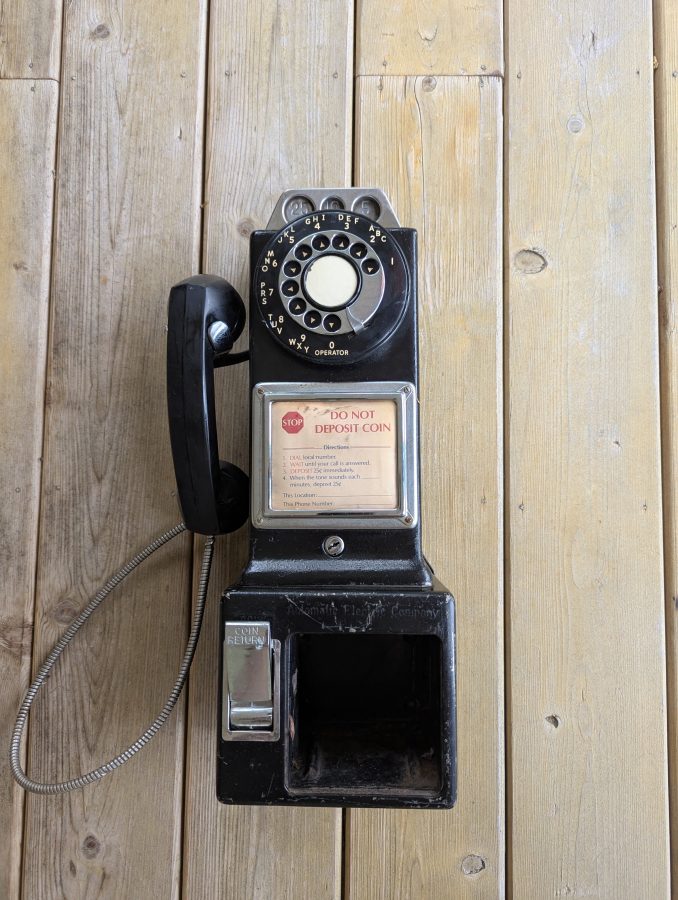
Recently, I saw a video about an engineer in Vermont who was fixing and placing single slot pay phones at welcome centers around the state. These are functioning as courtesy phones for travelers to use, free of charge. That is an interesting project.
My father worked for New York Telephone Company in various capacities from 1954 until he retired in 1988. We had a number of old telephone sets around the house which were removed from homes, old farms, businesses, and the like. One such telephone was a three slot pay phone from The Hitchcock estate in Millbrook, NY. This was a very unique item, as it dated from the Timothy Leary period of residence. It had white, blue, pink, and purple swirls painted all over it. At some point, G. Gordon Liddy, who was the then assistant District Attorney for Dutchess County, rented a Cessna and flew over the house to obtain a search warrant. After Leary was arrested, the group of LSD experimenters living in the estate house soon dissipated. My father went in and removed the pay phone. He said that those folks were living in squalor, “like filthy animals.” In fairness to my father, his Korean War experience while serving in the Marine Corps may have slightly colored his opinions about such things.
We called it the “hippie phone.” I believe it was a Western Electric model. After I moved out of the house I grew up in, all of those things disappeared.
I would have liked to have kept that pay phone.
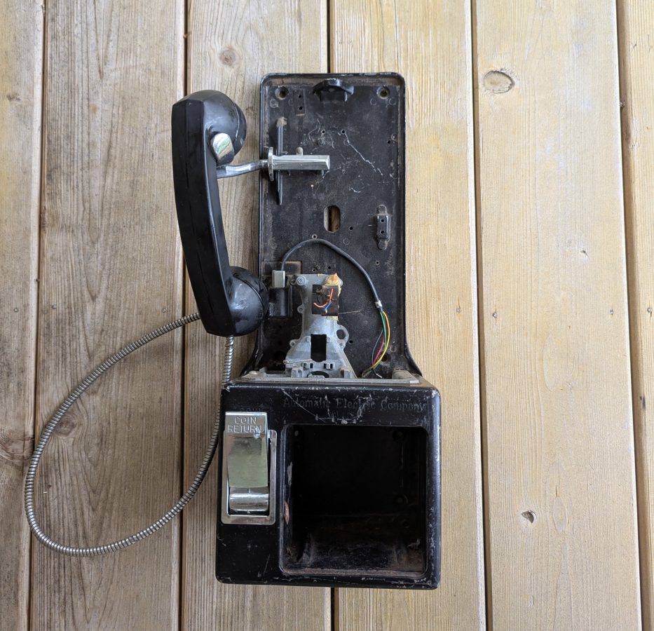
All of that got me thinking about pay phones. Could there possibly be a similar pay phone for sale on eBay? Yes, there could. But they all seemed terribly expensive. Except for one reasonably priced unit, which I purchased. This is an Automatic Electric pay station, which is almost identical looking to the Western Electric unit from the same era.
Automatic Electric 3 slot pay station
When it arrived, I discovered the reason why it was less expensive; it is missing all of the internal parts. I was a little irritated by this, but soon discovered that it was typical. The phone company often removed the coin collecting relay and vault door as soon as the phone was taken out of service. The hook switch, induction coil, condenser, terminal board, and wiring harness were all removed, probably to be used to restore another phone.
No internal parts
Fortunately the coin slot and coin validating mechanism are still in place. If you drop a dime you will hear a nice “ting ting.” A nickle will result in a single “ting,” a quarter will make a satisfying “bong” sound from the gong.
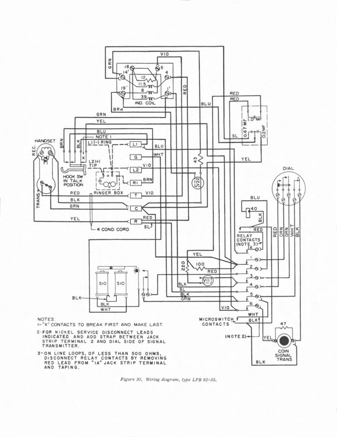
I found a manual on line for the Automatic Electric pay phones which had a wiring diagram with the wire colors.
Automatic Electric 82-55 wiring diagram
Unfortunately, there are no part numbers. I had a difficult time trying to figure out the correct parts to search for. I finally stumbled upon a Youtube video where someone was tearing down one of these units. That revealed the OEM part numbers for the coil (D284476A) and condenser (D68850A). With that, I was able to find the original manufacture’s assembly which included the hook switch, induction coil, wiring harness and terminal strip for a reasonable price on The Old Phone Shop website. I also ordered the condenser and a ringer (these phone had no internal ringers as manufactured). There is an option to buy an entire modern network board, but I wanted to keep this as original as possible.
The wire harness from the rotary dial was also missing. I used some wire from Belden 9423 cable to make those connections, keeping the wire colors shown in the schematic.
Next, I purchase a Pulse Dial to Touch Tone Converter. On POTS lines, most CO switches still recognize pulse dialing. However, POTS lines are expensive and I do not want to pay for one at my house. The answer is an Analog Telephone Adapter (ATA) with this converter. I purchased a Cisco/Linksys 2102 unlocked ATA on eBay for $16.00. Lowest cost DID number I could find is about $8 – 9 per month. There are directions on how to DIY a pulse dial to touch tone converter, but I simply purchased one on Amazon.
A bit about Plain Old Telephone Service (POTS) lines. It is a circuit switched data system. These systems are very simple and consist of a two wire circuit between the Company Office (CO) and subscriber Point of Presence (POP) known as a local loop or subscriber loop. The circuit is made by closing the Hook Switch. When the circuit is open, there is nominally -48 VDC across the Tip and Ring. When the Hook Switch closes (goes off hook), that drops to about 7-9 VDC. When the circuit closes, the CO switch detects a current flow and puts a Dial Tone consisting of two tones, 350 Hz plus 440 Hz on the loop. The subscriber can then dial a number and be connected to another party through the switch and what ever local or long distance carriers are needed to complete the call. On the other end, the CO switch will put a 20 Hz 90 VAC ring voltage down the line to ring the receiving subscriber’s phone. If the distant station is already off the hook, a busy signal is sent to the call originator, consisting of 480 and 640 Hz tones.
Internal to every POTS phone is a network consisting of an inductive coil and a capacitor or two and a resistor or two. The purpose of this is for line equalization and to create a two wire to four wire hybrid. The four wire hybrid is what feeds audio to the ear piece and receives audio from the handset microphone. It cancels echo from the distant station and provides a small amount to “side tone” or audio from the microphone so the user can hear themselves when they talk. The audio pass band is from about 300 Hz to 3,300 Hz.
In addition to that, some type of dial mechanism is required; either pulse or DTMF (Dual Tone Multiple Frequency). Pulse dial interrupts the closed Hook Switch in rapid succession (39 ms on, 61 ms off) to send a number to the switch at the CO.
DTMF consists of the following tone pairs:
Number
Tones (Hz)
Number
Tones (Hz)
Number
Tones (Hz)
1
697, 1209
2
697, 1336
3
697, 1447
4
770, 1209
5
770, 1336
6
770, 1447
7
852, 1209
8
852, 1336
9
852, 1447
*
941, 1209
0
941, 1336
#
941, 1447
Provided the local loop stays intact, the POT system is extremely reliable.
The Analog Telephone Adapter (ATA) converts a POTS from a circuit switched system to a packet switched system, then uses the public internet to complete a call. ATAs do not accept pulse dialing, hence the Pulse Dial to Touch Tone Converter. Where ATAs often fail is the ring voltage and tip/ring polarity.
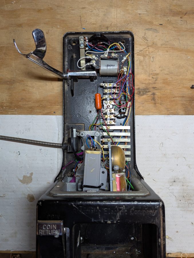
Back to the task at hand: When the parts arrived, they all matched the mounting holes in the back plate of the phone. That is a good sign. I took the rotary dial off and put the new wires on. I also took the time to de-gunk and clean the mechanical parts of the rotary dial, then re-oiled it. It works as well as the day it was manufactured. The old mechanical phone system parts were built to last a long, long time.
The Hook Switch, Terminal Board, harness and condenser all fit into the phone almost perfectly. The condenser was hitting against the coin validator which didn’t seem quite right. I moved the condenser down to where the coin relay was located so it didn’t get scratched up.
Automatic Electric 3 slot pay station with parts installed
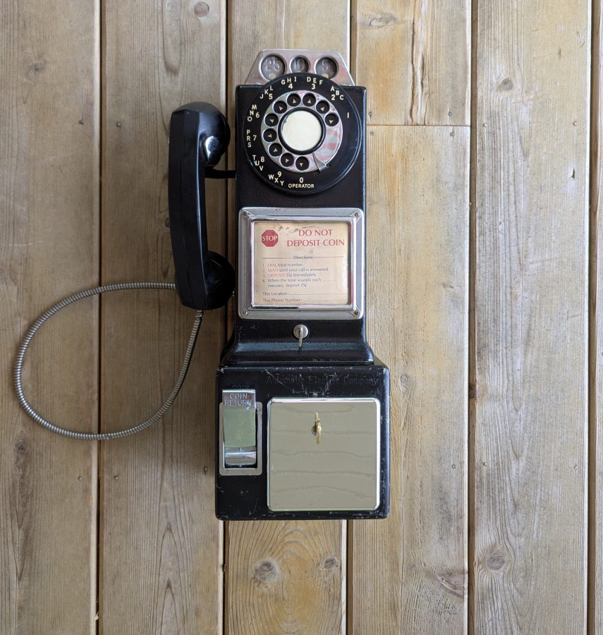
I also bought a small ringer, which I installed where the coin relay was. I purchased a replacement vault door and lock. This is a plastic unit, not a OEM part, however, it does the job and I am not worried about anybody prying the vault door off and stealing all the change. Putting it all together, it looks great! Now I need to find a used phone booth to put it in. There are a few of those on eBay as well, but very pricey.
Automatic Electric 3 slot pay station, restoration complete
I took the phone to the office and plugged it into a POTS line and called my cellphone. The old carbon element microphone might need to be replaced, other than that, everything works great. It is now worth considerably more than I paid for it, which is also nice.
We just finished our 3rd annual February ice storm. It is becoming somewhat of a tradition in these parts. After shoveling the driveway this morning, I sat down to enjoy my nice hot coffee. While doing that, I figured I would check some of the transmitters to see how things were going. That is when I noticed this:
The reflected power is much higher than normal indicating potential issues with the antenna deicers. I knew something was wrong after a quick call to the Burk, which stated the deicers were on. A quick double-check showed that the reflected power had increased by another 75 watts, so a nice drive to the transmitter site was in order.
Road to the transmitter site
Indeed, the controller had turned on the antenna deicers.
Antenna deicer controller
Using a clamp on amp meter, I saw almost no current on either leg of the 240-volt circuit. In the meantime, the backup antenna had 2 amps on each leg, which is normal. Then I noticed this:
Antenna deicer relays
The relay on the right shows signs of overheating.
I moved the Main Antenna circuit over to the aux antenna relay to get things going again. The current on each leg of the main circuit is 4.2 amps. Over the next 45 minutes, the reflected power returned to normal.
Other transmitter sites to the north in Albany have had similar issues. Unfortunately, those antennas do not have heaters or radomes. Thus, the only remedy is reducing power until the transmitter stays on.
I also noticed that when there is an antenna problem, the station does not sound as good as it normally does because of the bandwidth restrictions adding distortion in the frequency domain.
I don’t know how many parts there should be in this series, five is a guess.
While some AM stations surrender their licenses to the FCC, others are undergoing needed repair work to stay on the air for a while longer.
WBEC-AM, Pittsfield, MA
WBEC-AM in Pittsfield Mass is the topic of today’s post. This station is Non-Directional day, Directional Night with a two-tower array. This site was built around 1956 when the station moved from Eagle Street, near downtown Pittsfield.
WBEC-FM backup antenna, mounted on WBEC-AM array
This Shively 4-bay antenna is the backup antenna for WBEC-FM. It is being replaced with a 3-bay antenna. The new antenna will serve W277CJ which is relocating from downtown and as a backup for WBEC-FM. A set of signal strength measurements for the nighttime directional array is required along each of the three monitor point radials before and after that work is completed.
The issue these days is the nighttime directional system, which is somewhat erratic when in use. The towers are 180 degrees tall with 35 degrees of top loading making the towers 215 degrees tall or just under 5/8 wavelength. As such both current and voltage are near maximum at the tower base, which makes them very sensitive to any changes at the base.
First, there was an issue with the tower lighting system. It seems that somewhere on the non-reference tower, the beacon conductor is shorted to the tower. When the tower lights are on, the loop current rises and falls in time with the beacon light. Because these are series excited towers, the fuse for the beacon does not blow, but the 60-cycle AC current does show up on the tower loop current reading. Rather than try to repair things on an almost 70-year-old tower light system, it was decided that both towers should get new LED lighting systems.
Next, mice chewed through several AC supply cables for the phasor at the base of tower #1. When switching from day to night patterns, some or all of the contactors would not move or get hung up between states taking the station off the air.
It is unfortunate that the phasor is at the base of one of the towers and the antenna monitor is back inside the building with the transmitter. It takes two people to make adjustments to the nighttime array.
The tower #1 ATU/phasor building is full of old unused equipment, a mouse haven. It also blocks access to several points that need to be sealed up to keep mice from getting in in the first place.
Slatercom LED light system controller
What is interesting is, that the original wiring and photocell failed at some point, and someone simply wired up a new photocell, leaving all of the old equipment in place. Thus, it became difficult to troubleshoot and ID the conductors in use vs the ones abandoned. With the replacement of the tower light systems, I decided that everything must go. The new Slatercom A-1 replacement lighting systems have individual controllers each with its own photocell. In addition, they have wireless links for tower light monitoring. It is great to get rid of the dry pairs going back to the transmitter room, which always creates RF and lightning headaches.
The station will also be saving some money on electricity. The new lighting system draws 88 watts total vs the old incandescent system which drew 1,000 watts with a 50% duty cycle on the beacons. The old system was on all the time due to photocell failure. I estimate they used 17,520 KWh per year on tower lights, at $0.20 per KWh which is $3,504.00 per year vs $308.00 per year for the LED systems. The added benefit of LED fixtures is that they should last much, much longer than incandescent fixtures.
WBEC-FM Harris FM1H3 transmitter scrapped
This lovely Harris FM1H3 was donated to the scrap yard. I believe that this is the second transmitter (1974) for the original 105.3 WBEC-FM which signed on in 1967.
Tower #1 ATU building cleaned out
The building clean-out, unwiring, and rewiring process took about a day and was well spent, in my opinion. Working in a building that is not full of mouse nests, droppings, and stinks like mouse urine is nice. I plugged several holes in the building with stainless steel pot scrubbers and spray foam.
Nautel Amphet 1 transmitter
After removing and replacing the old tower lighting system, the Nautel Amphet 1 transmitter would not run into the nighttime array. This was likely due to the changes at the tower base. I used a VNA to measure each tower’s base impedance which is 42.5 ohms and -j139, 44.5 ohms -j155 respectively.
WBEC Tower #1 base impedanceWBEC Tower #2 Base Impedance
Then the daytime and nighttime common point impedance was measured. Both were off, but the nighttime was more so than the daytime. I adjusted the R and X until both were reasonable and the transmitter would run into both patterns. According to Nautel, the Amphet 1 transmitter runs best into a load of 50 ohms j+5 measured at the transmitter output.
WBEC antenna system schematic
The daytime antenna is non-directional and there is no “common point,” however, there is an R and X adjustment in the phasor for the daytime tower. According to the file I found, it used to be a directional daytime until 1967, when they could make the daytime antenna non-directional. It is an interesting setup.
With the array properly adjusted, readings could be made along the monitor point radials. This station has three monitor points, two are in the nulls and one is in the main lobe. It is the nulls that are the greatest concern. Fortunately, much of the documentation from the original proofs was found in a filing cabinet. While the maps are nice, they date from 1950 and are woefully out of date. However, I was able to find good reference points on the 1950 maps and redraw radials on a Google map.
I found these photos of the monitor points as they were in 1956:
1956 photographs of an engineer making field strength measurements
Those were great because I was able to verify the locations of the monitor points today:
243-degree radial monitor point, 2024
Based on that, I made three maps with radials on the monitor point azimuths:
WBEC-AM Pittsfield, MA 243-degree radial ten measurements
The consulting engineer wanted about 10 readings on each radial. I created an individual map for each radial, marking points where the radial crosses a public road. When it came time to do the monitor points, I loaded the map into my smartphone and followed the directions to each point. It worked very well.
We will return and make post-installation measurements once the new FM antenna is installed.