Modifying the old Broadcast Electronics Transmitter

In the previous post, the issue with the WVOS-FM transmitter was detailed: The PA feed through/bypass capacitor had arced to the PA cavity causing lots of unwanted off-air time. When I went to order the replacement parts, of course, they were not available. It seems that Broadcast Electronics changed the design of its transmitters in the late 1980s to use a different feed-through arrangement.

They were nice enough to send us a nifty retrofit kit; BE part number 959-0272 which replaces BE part number 959-0115.  If interested, the six pages of installation instructions are available here, for your reading pleasure.

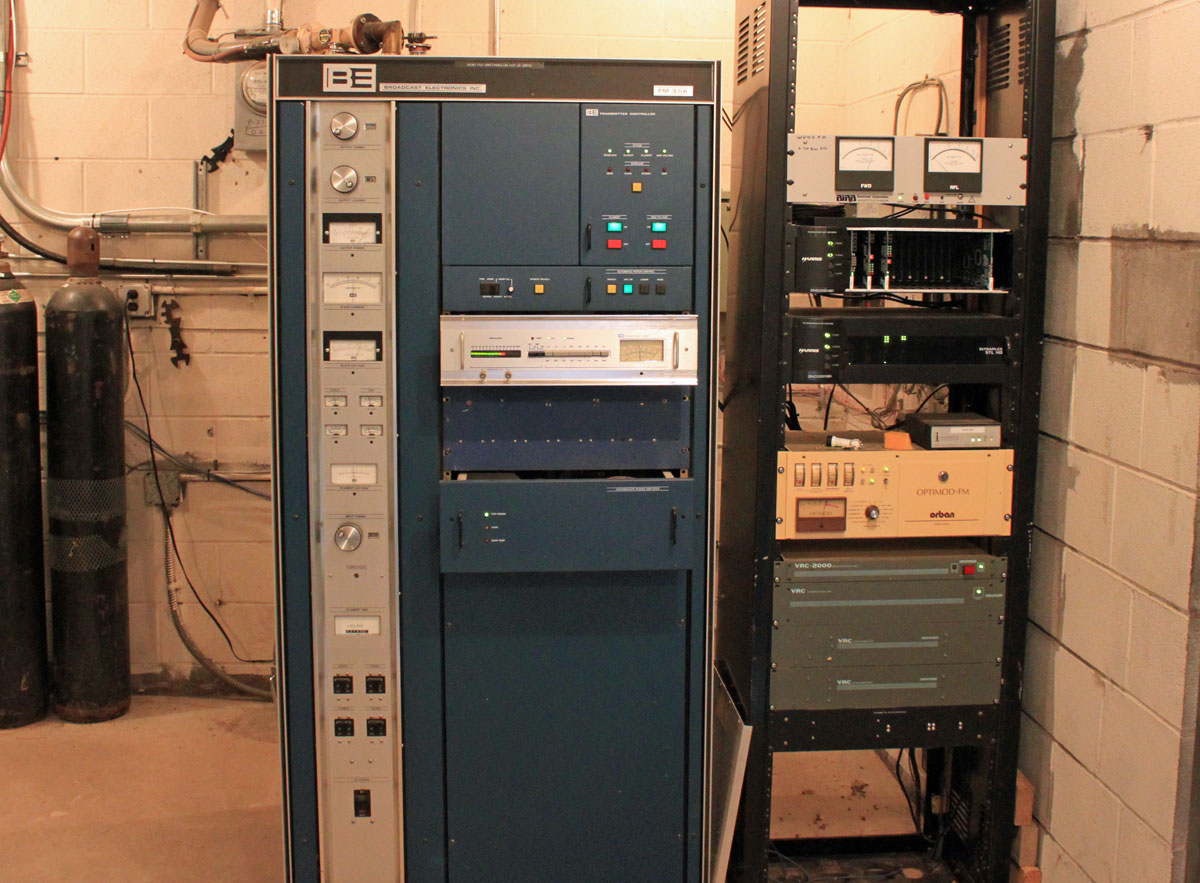
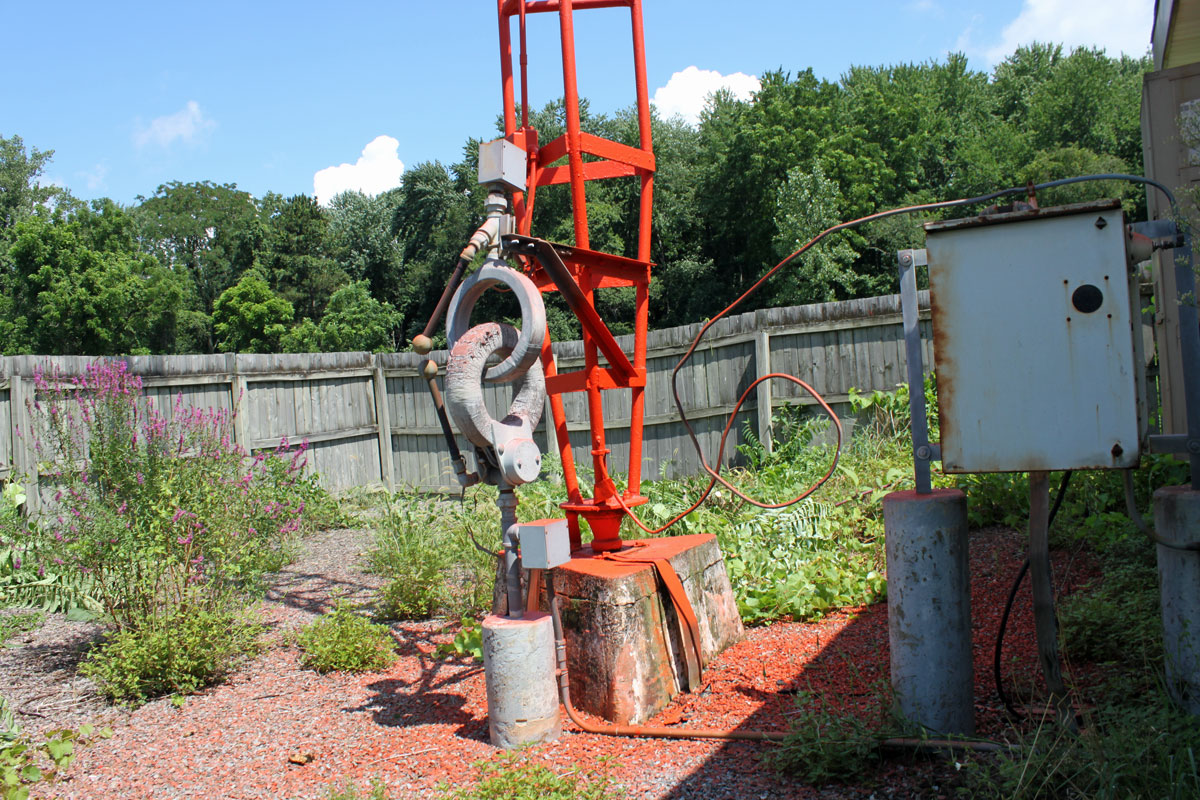
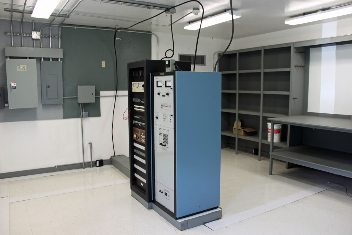
The retrofitting itself was quite the job; drilling six mounting holes and one one-inch feed through hole in the PA cavity, mounting the new feed through housing, rewiring the high voltage connection to the tube and back to the HV bleeder assembly, etc.  What with all of the drilling, sawing, filing, deburring, and whatnot, I began to wonder if the transmitter would ever run again.  This is the transmitter before the modification:

Broadcast Electronics FM3.5A PA cavity

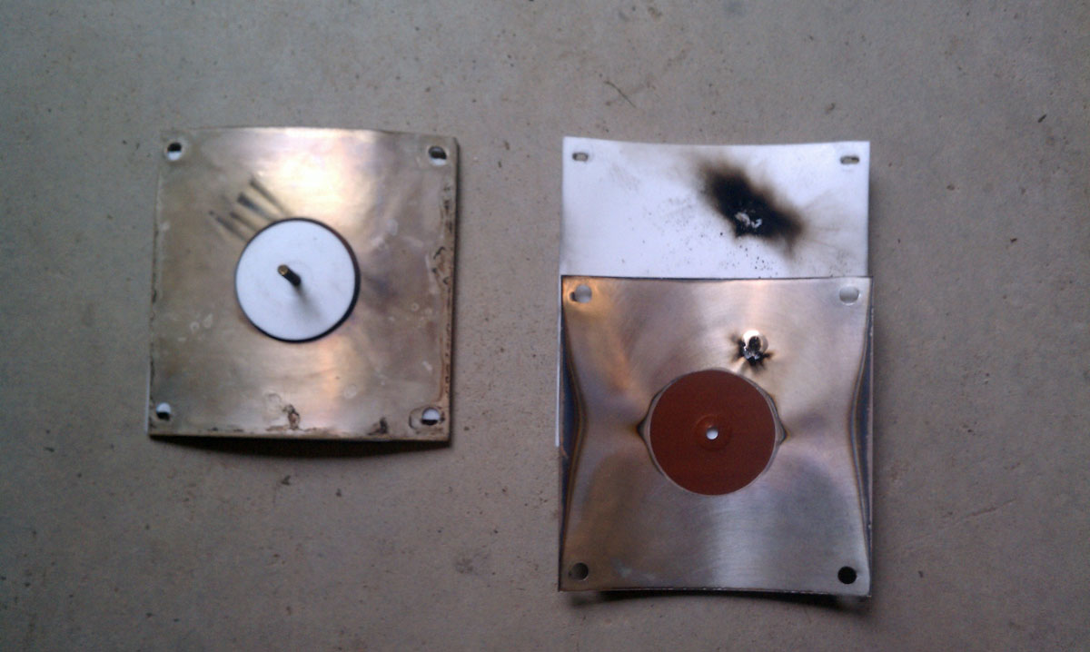
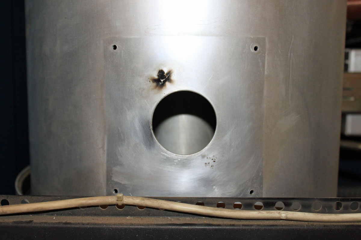
This is the old high voltage feed through hole, arc mark clearly evident.

Broadcast Electronics FM3.5A old high voltage feed though

This is the modified feed through/bypass configuration.

Broadcast Electronics FM3.5A new PA feed through capacitor
Broadcast Electronics FM3.5A new PA feed through/bypass capacitor

While doing this work, I removed the tube and put a plastic sheet in the bottom of the PA cavity and around the HV parts at the bottom of the transmitter.  Somehow, getting aluminum filings in the tube socket seemed like a bad idea.  I also thoroughly vacuumed out the entire transmitter once all of the metal work was done.

I removed the Kapton capacitor plates from the old feed-through arrangement and reinstalled the Teflon insulating plates to keep the air flow out of the tube cavity going in the correct direction.  The new capacitor looks very beefy, perhaps it will never fail again.

Once the installation work was done, I brought up the transmitter first with no screen and no connection to the tube anode.  Then with the tube connected, and finally with the screen supply turned on.  The tuning needed a brief touch up but all in all, the transmitter came up and ran well with the new feed-through arrangement.

The old Broadcast Electronics Transmitter

Alternate title: More blown-up stuff

This Broadcast Electronics Fm 3.5A will be thirty years old in April. We should have a party!

Broadcast Electronics FM 3.5A, WVOS-FM, LIberty NY
Broadcast Electronics FM 3.5A, WVOS-FM, Liberty NY

Unfortunately, this transmitter is not doing too well these days. The PA high voltage feed through capacitor has arced over to the PA cavity, causing the station to be off the air.

BE FM3.5A HV feedthru capacitor
BE FM3.5A HV feed thru capacitor

Naturally, this happened over the weekend, parts will not arrive until Tuesday at the earliest, and the station is without a backup transmitter.

Obviously, trouble shooting this was a two-person job.  Never work alone on HV equipment.  The symptom was the main circuit breaker was tripping after the HV on command.  Starting from the transformer end of the HV power supply circuit and working toward the anode of the PA tube, all of the components were tested by isolating each component then turning the HV on.   Special care was taken to discharge all components after each test.  The capacitors and bleeder resistors were reconnected at the same time.  There is too much risk involved with charged 8 KV capacitors and no way to bleed that charge to ground.  Everything worked up until the PA cavity was reconnected (without the tube), then the breaker tripped again.  Thus, the above feed-through capacitor was removed and disassembled, revealing the damage.

The question is, how long should transmitting equipment last? After all, if one were running a freight delivery company, you would not be driving around in thirty-year-old trucks, would you? No, not if you wanted to stay in business. Like all electro-mechanical equipment; transmitters, consoles, STLs, antennas, computers, etc wear out.  A smart plan would be to have a replacement schedule and be putting money into a capital equipment replacement fund.   Equipment life varies with the type.  Getting twenty years out of a main transmitter is a pretty good service life, going beyond that is pressing one’s luck.  Ten years on any one computer is a very long time.  Then there are certain transmitter manufactures that drop support on older units, which makes it difficult to keep them operating.  Owners and managers need to be cognizant of the age and condition of critical infrastructure.  As field engineers, how much time do we devote to keeping antiquated equipment running, or should we even be servicing it at all?  As independent contractors, we incur a liability whenever we touch something.  Where does the ownership’s responsibility lay in providing safe, functional equipment for their stations?  All interesting questions.

Wireshark; what is it good for

Wireshark is a packet protocol analyzer that is free for download and runs on Windows, Linux, BSD, OS X, and Solaris.  In the evolving broadcasting studio, computer networks are the backbone of the facility. Not just on the office side of the house, but also on the broadcast origination side as well. Today, almost everyone uses some type of computer automation system running on a network. In addition, new technologies such as AoIP consoles, VoIP phone systems, audio and video routing, remote control, off-site monitoring, audio processing, etc continue to develop.  Because of this, more and more broadcast engineering work is falling into the computer and networking realm.

Like anything else, networks can fail.  Failure modes can originate from both the physical side, e.g. wiring, connectors, patch bays, network interface cards or the software/protocol side.  Being able to diagnose problems quickly and take remedial action is important.  On the networking side, if a physical problem has been ruled out, then the problem exists with a protocol.  That is where Wireshark becomes useful; it takes the guesswork out of networking protocol troubleshooting.

Wireshark packet protocol analyzer has the following features (from their website):

  • Deep inspection of hundreds of protocols, more are in development
  • Live capture and offline analysis
  • Standard three-pane packet browser
  • Versions available for Windows, Linux, OS X, Solaris, FreeBSD, NetBSD, and other OS
  • Captured network data can be browsed via a GUI, or via the TTY-mode TShark utility
  • Filtering by protocol, IP address, MAC address, frame type, sequence number, etc
  • VoIP analysis
  • Read/write many different capture file formats: tcpdump (libpcap), Pcap NG, Catapult DCT2000, Cisco Secure IDS iplog, Microsoft Network Monitor, Network General Sniffer® (compressed and uncompressed), Sniffer® Pro, and NetXray®, Network Instruments Observer, NetScreen snoop, Novell LANalyzer, RADCOM WAN/LAN Analyzer, Shomiti/Finisar Surveyor, Tektronix K12xx, Visual Networks Visual UpTime, WildPackets EtherPeek/TokenPeek/AiroPeek, and others
  • Capture files compressed with gzip can be decompressed on the fly
  • Live data can be read from Ethernet, IEEE 802.11, PPP/HDLC, ATM, Bluetooth, USB, Token Ring, Frame Relay, FDDI, and others (depending on your platform)
  • Decryption support for many protocols, including IPsec, ISAKMP, Kerberos, SNMPv3, SSL/TLS, WEP, and WPA/WPA2
  • Coloring rules can be applied to the packet list for quick, intuitive analysis
  • Output can be exported to XML, PostScript®, CSV, or plain text

A few things to keep in mind with the physical connection.  Connecting a computer to a switch port will establish a collision domain between the switch port and the computer which is also called a network segment.  The computer NIC will see all traffic on that collision domain and all broadcast traffic on the network or sub-network that the switch is attached to.  If there is a suspected problem with a particular network segment, the Wireshark computer needs to join that collision domain.

Creating a network segment tap with a hub

This can be done most simply by installing Wireshark on the host in that domain. Alternatively, a hub can be used to add another host to the collision domain.  Or, if it is a managed switch, there may be a provision to send all traffic on the switch out of one designated port.  This is called ‘port mirroring’, ‘port monitoring’, ‘Roving Analysis’ (3Com), or ‘Switched Port Analyzer’ or ‘SPAN’ (Cisco).

Network diagram with managed switch

A quick tutorial on what to look for when using Wireshark, Part A:

Part B:

And briefly, that is how it is done.  There are many more videos on youtube and elsewhere if interested in learning more.

WKNY, Kingston, NY

This is another one of those, ahem, AM success stories. WKNY is on 1490 KHz, 1,000 Watts day and night from a transmitter site that is located very close to its target audience of Kingston. It signed on on December 16, 1939, broadcasting 100 watts on 1500 kHz according to the Broadcasting Yearbook 1940 edition.

WKNY transmitter site location

The transmitter location is the key to this station’s good signal over Kingston. Even though it is a class C AM station when driving around the Kingston city limits there is no electrical interference or nighttime co-channel interference.  The reason for this is that most of the city limits are within 2.5 to 3 miles (4 to 4.8 km) from the tower.

WKNY transmitter building and tower

This is the original transmitter building and tower.  Like many old AM transmitter sites, this one is located in a low, swampy area.  The tower is electrically tall for 1490 KHz, at 92 meters (305 feet)  it is 163 electrical degrees. Something else that may contribute to the station’s performance.

WKNY tower base
WKNY tower base
WKNY tower
WKNY tower

WKNY tower, a typical design of a uniform cross-section guyed tower from the late 1930s to late 1950s.

WKNY transmitter
WKNY transmitter

WKNY transmitter. Another Nautel ND-1 series transmitter. Nothing ever breaks or goes wrong.

Air studio, WKNY Kingston, NY

The air studio has an AudioArts R-60 console. For an inexpensive audio console, these things sure seem to last for a long time. I think this one was put in in 1997.

Talk Studio, WKNY KIngston, NY

A small talk studio is used to originate local programming of interest. This morning, I was listening to “Speak Out With Jody McTague,” a local interest program that was discussing the impacts being felt in the Kingston area due to the “Affordable Health Care Act.”

WKNY production studio

The production studio has a rather old Harris rotary pot console from the 1980’s.

Of course, all of this equipment makes radio transmission possible, but what makes radio itself is the local people working at the station and bringing relevant information to the area.  I know a lot of very smart people are working on the “solution” to the AM problem.  It really has to do with the programming.