Another trove of surveillance documents reveals some interesting technical aspects of spying in the modern age:
Gigabit cooper network tap
What we have here is a copper wiretap. This allows some telco or ISP to split an ethernet feed, and send one output on its merry way, while the other output goes to? If not interception and collection, I don’t rightly know what else this device is designed for.
There are many many more like this on the WikiLeaks website. Have any doubts about how deep the internet surveillance goes? Spend a few minutes poking around, it is an eye-opening experience.
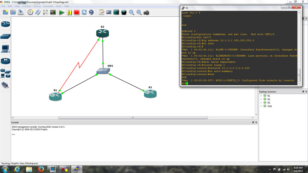
I have been working with GNS3 (Graphical Network Simulator) in some of my classes. It is a fine tool with which one can build simulated computer networks using various routers and switches. The software program itself is free, however, the Cisco IOS images are not included and must be found elsewhere due to copyright issues. This detail is a bit of a pain, but not too bad. Once the program is set up and the appropriate IOS images are loaded, the console functions exactly like whatever router is being simulated. This includes running whichever terminal program is preferred, e.g. hyperthermia, putty, or if using the Linux version, x-term, etc.
GNS3 screenshot, topology, and router console
The advantages to this over something like Cisco’s Packet Tracer program are many. In Packet Tracer, certain functions are locked out and generally there is only one acceptable way to complete any given task. With GNS3, the IOS is fully functional, which means that experimentation and failure are available to play with. Failure is a great way to learn things in any hands-on environment. The advantage of virtual failure is that only you know about it.
For real-world applications, this means that router and switch configurations can be created, tested, and tuned ahead of time and then loaded into working devices, saving downtime and potentially handfuls of hair.
A few things about using GNS3, the PC idle tuning is required. Each instance of IOS assumes that the entire processor is available to use, thus starting several routers can work a PC’s processor to 100% and windows will never fully recover. Secondly, when starting each router, wait 10 to 20 seconds before starting another one. Again, this has to do with the way IOS uses processors. Also, to save time, store the IOS image as a decompressed file. This saves quite a bit of time on startup. Finally, do not forget to copy the running config to startup-config. Even though GNS3 says it is saving the router configs, it does not save the running config unless you issue the copy run start command, just like a real router.
Update: Apparently this is quite interesting to a number of people. I have rescanned the manual, properly compressed it and which you may find it here.
Found this manual at one of the older transmitter sites:
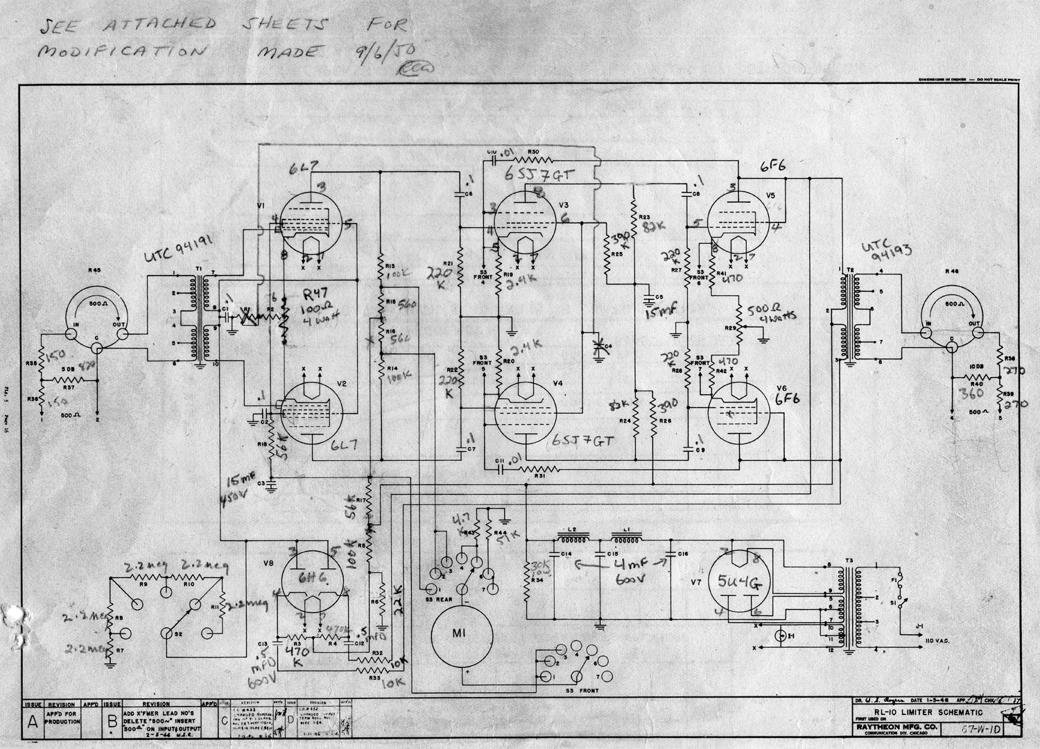
As this is an older design than either the Gates Sta level or the Collins 26U, it may not be as useful to tube audio enthusiasts.
Raytheon RL-10 Schematic diagram
The main issue with the Gates and Collins unit is the GE 6386 remote cutoff triode used, which were great tubes, but very difficult to come by these days. This design calls for a 1612 or 6L7, which is a pentagrid amplifier. Feedback is provided by the screen of the following stage, a 6SJ7GT. Anyway, perhaps it will give somebody some idea of how to make a good tube compressor limiter.
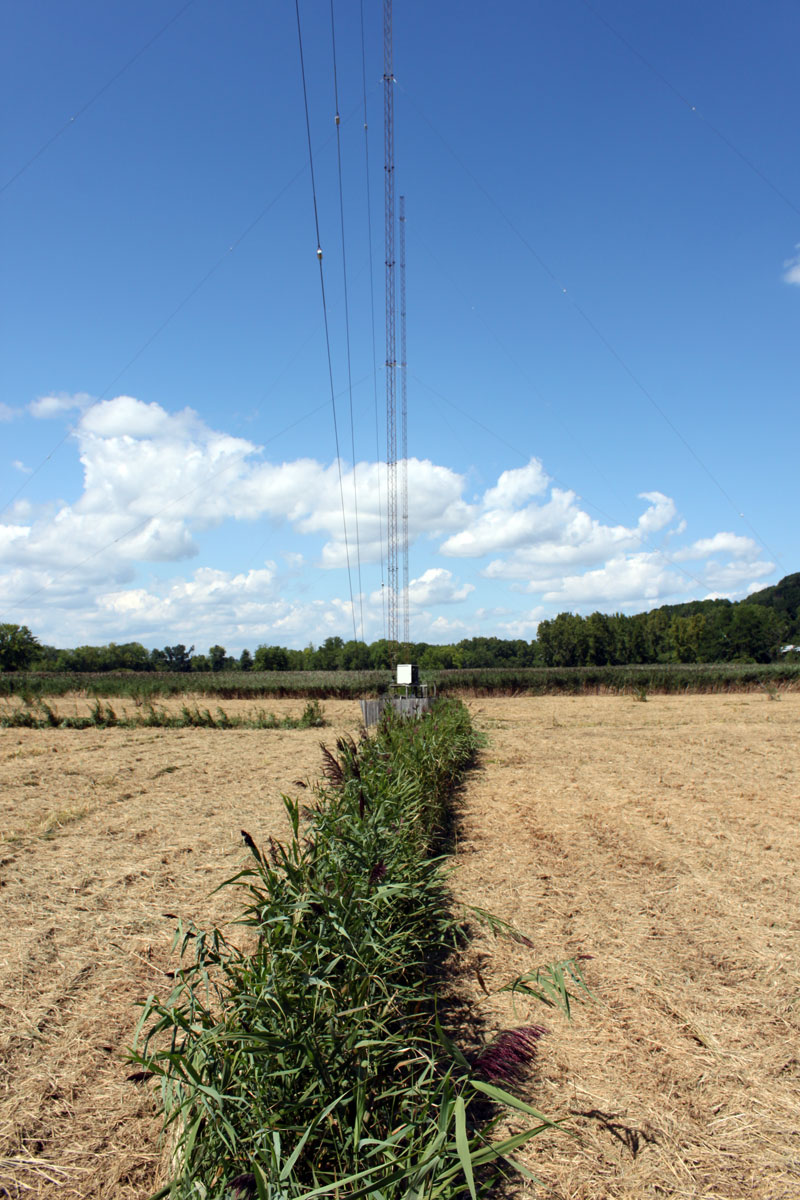
Working on another AM directional station (WGDJ) which was damaged by lightning recently. In this case, the antenna array controller ceased working and one of the towers in the daytime pattern was out tolerance. Before we stared working, I told the owner to have all the vegetation cut down around the towers. This is what we ended up with:
WGDJ catwalk, East Greenbush, NY
I can’t really fault them for this, but it does make work more difficult. That strip of tall green grass; that is the catwalk. The grass itself is called Phragmites, which is tall, tough, reedy stuff that can scratch and cut person unaware. The array is in a low swampy area next to the Hudson River in East Greenbush, NY. Stepping off of the catwalk, one can sometimes find solid ground, or find ones feet six inches under water.
WGDJ tower one ATU clean out
This is Mike cleaning out the mice and bees nests out of the tower #1 ATU. Notice the can of bee spray in his back pocket. This was after he was stung in the forehead.
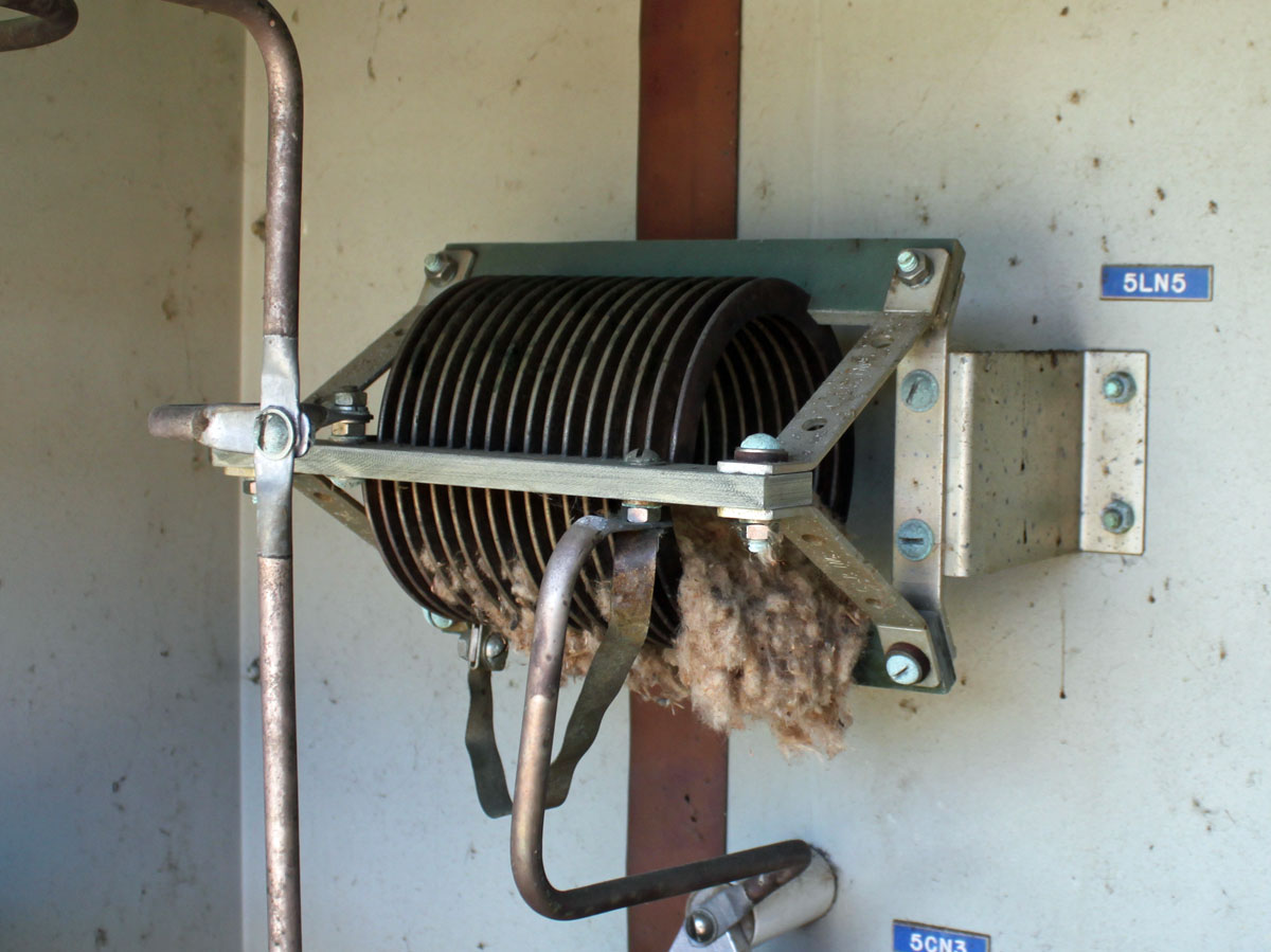
Mouse nest, WGDJ tower #5 daytime ATU coil
This mouse nest, at the attendant dead body in it, was responsible for a -10 degree phase shift in the daytime pattern for that tower. I hate cleaning this stuff out, it is a dirty, nasty job but necessary nonetheless. While doing this work, I wore gloves and a dust mask. The entrance hole where the AC power and control cables come into the bottom of the ATU was plugged up with some steel wool. There is still a bad capacitor in this ATU for the daytime array, that damage was likely caused by lightning.
At the end of the day, we repaired the antenna array/phasor controller; bad AC transformer and rectifier bridge and several bad logic steering diodes for tower 4 and 5, cleaned out all the vermin nests and isolated the remaining problem with the daytime antenna system. Parts should be in next week to finalize repairs.