Bucket Trucks and Landing Craft

Hopefully, that title is descriptive enough:

ATT bucket trucks, , mobilized via landing craft to Pleasure Beach

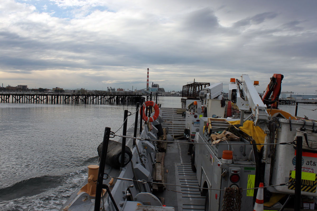
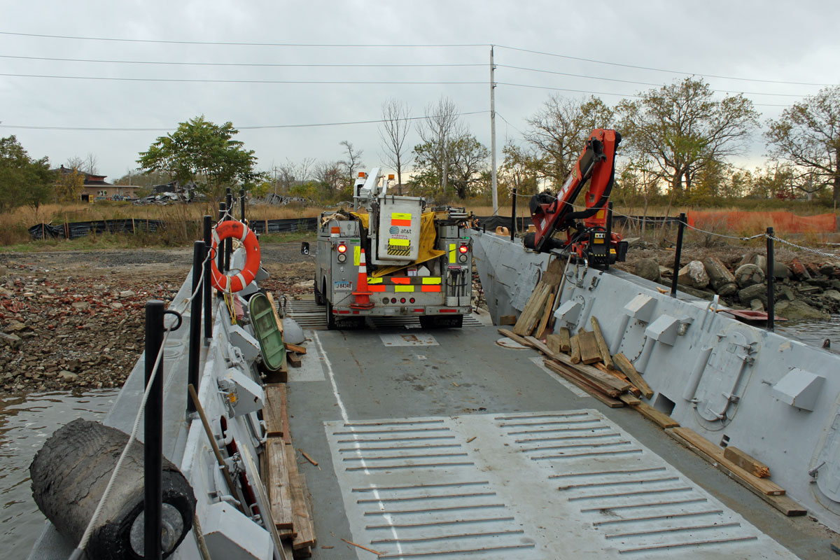
We loaded a couple of ATT bucket trucks on a landing craft and waged an assault on Pleasure Beach.  This is to finalize the repair work from Hurricane Sandy last year.  The other factor is the construction taking place on the Island.  The City of Bridgeport is constructing a park, which involves extensive repairs and renovations to the buildings.  Construction vehicles driving under the old lines have ripped them down several times, thus repairing the lines on the new utility poles was necessary.

ATT truck offloading

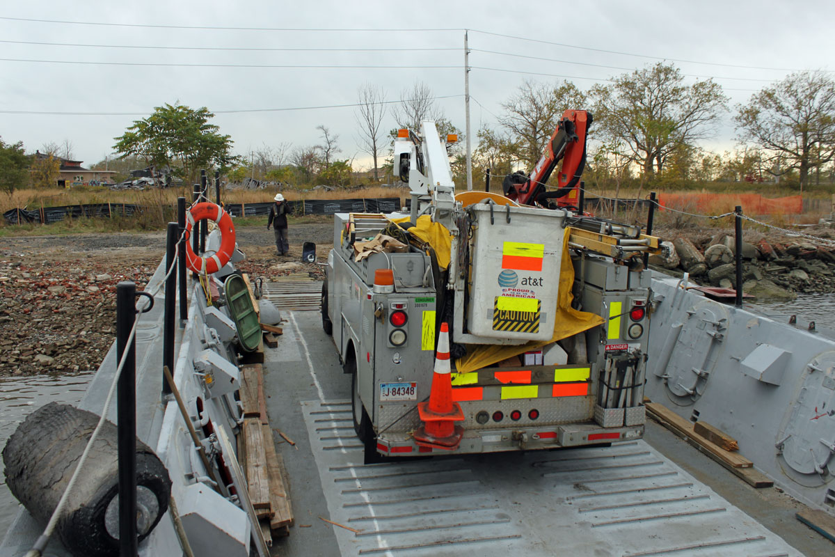
ATT is the LEC for the Bridgeport area, something they don’t do in most other parts of the country, from what I am told.

Landing Craft Challenger

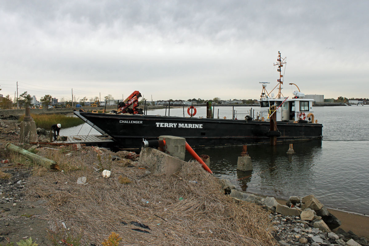
It took approximately four hours to complete this work and reload the trucks back on the landing craft.  The boat itself looks like a slightly modified LCM (Landing Craft, Mechanized), which was produced from 1943 onward.  This is an LCM-8.

WICC towers
WICC towers

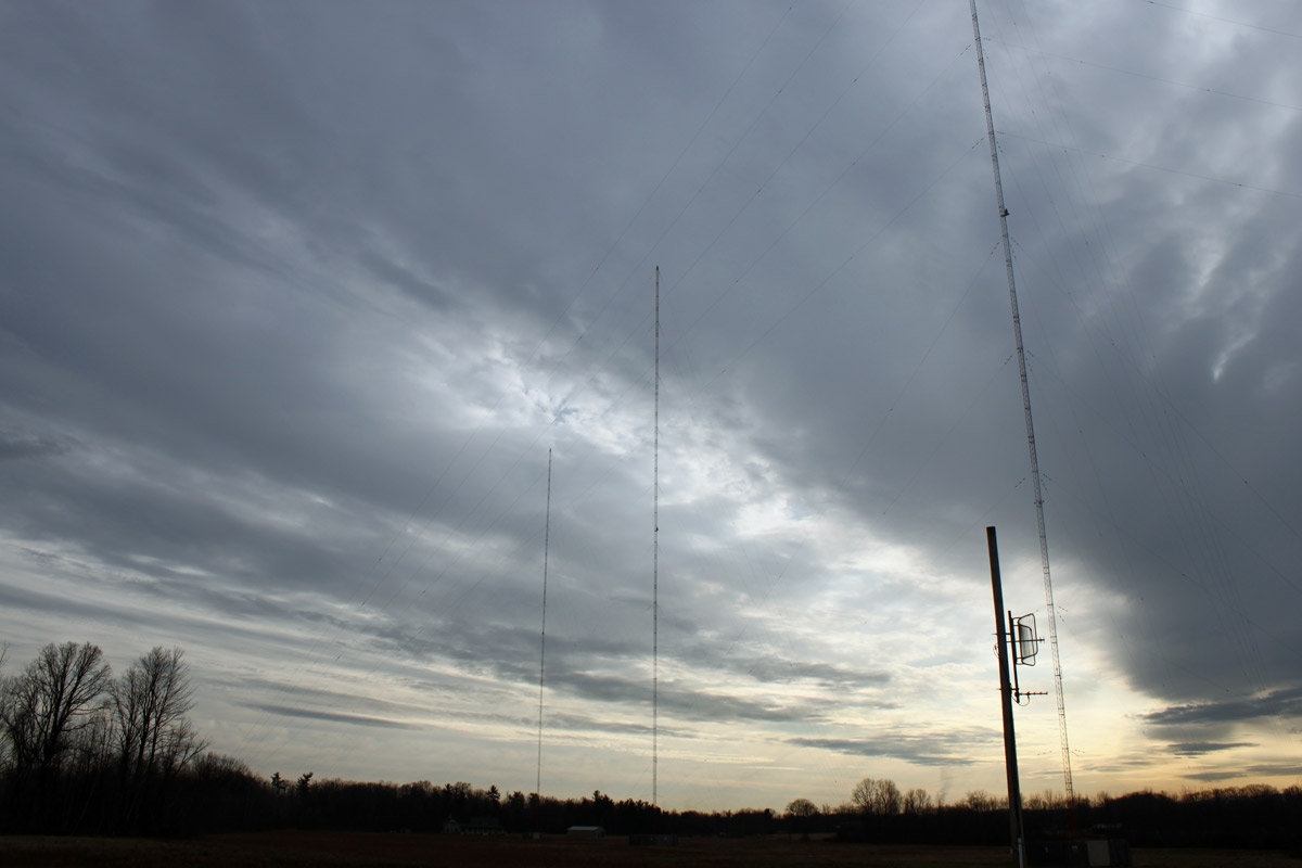
WICC towers almost in line, I was about one second too late with this shot. This would be “down the bore” of the daytime pattern into downtown Bridgeport.

WICC towers
WICC towers

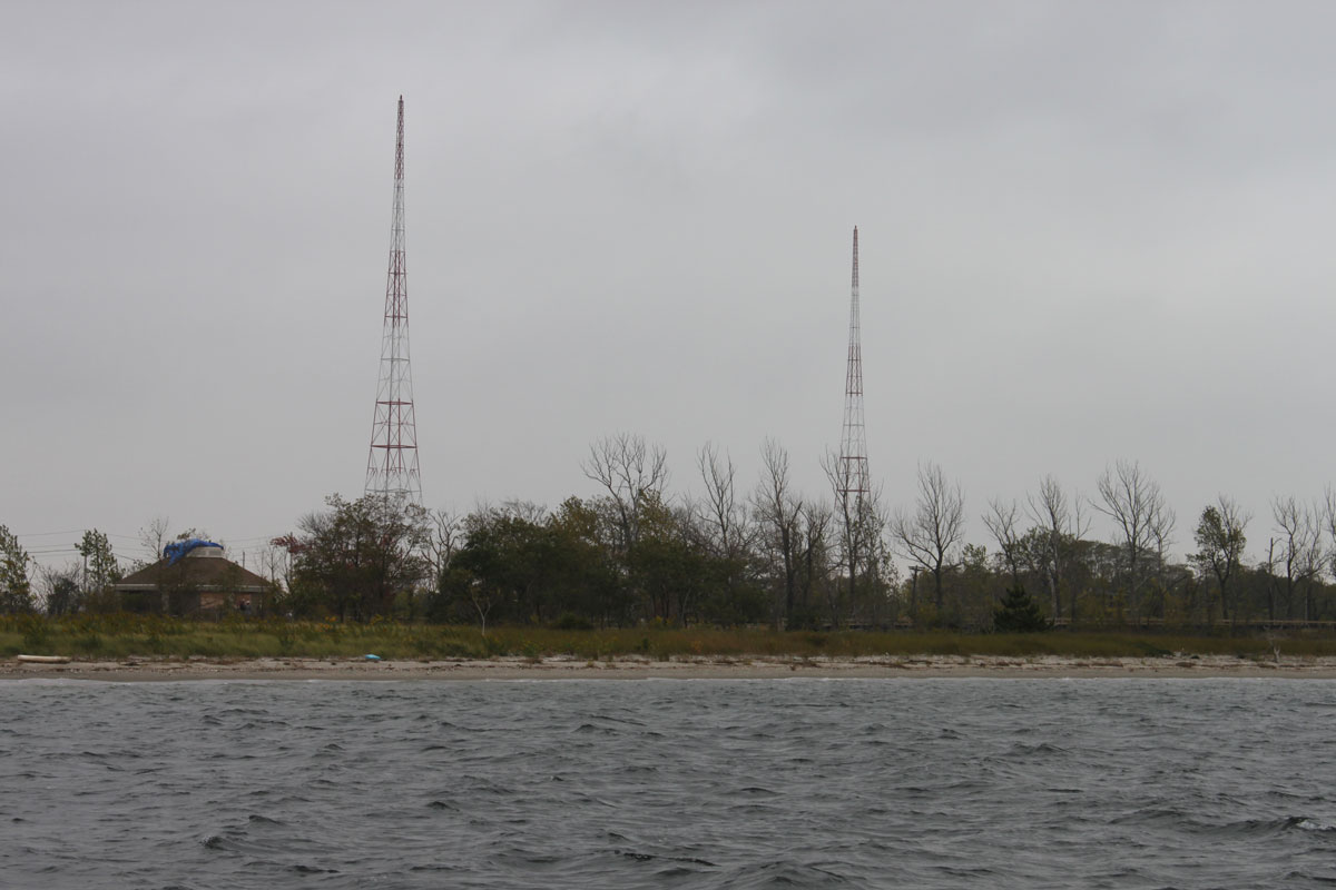
Another shot of the WICC towers. These were designed to hold up a horizontal T top wire antenna strung between the two of them.  At some point in the early thirties, somebody realized that the tower itself could be excited as a vertical radiator and the antenna configuration was changed. Up until the mid-1970s there was a horizontal wire which supported a third wire element hanging between the two towers, making it a three-tower directional array.  This was removed and it was then that the current phasor and two-tower DA-2 system was installed.

All in a day’s work.

Wikipedia Articles

Wikipedia-logo-v2

Type the call letters for almost any radio or television station in the country into a search engine, and the second or third result will be a Wikipedia article.

Try it.

This is both an opportunity and a burden.  Since Wikipedia articles place so well in most search engine results, it would be a benefit to radio stations to keep an eye on them; keep them up to date, make sure that no one vandalizes them, and fix them when they do.  Most importantly, keep the station website link and streaming link information up to date.  That is the burden but it is relatively small.

The opportunity comes from the ability to document the history of individual radio stations. On the grand scale, the history of any individual radio station is like a grain of sand on the beach. It is only pertinent to those who care.  But then there are those who do care and for some of us, reading a well-written, well-sourced article about some station we are familiar with is interesting.  To be sure, there are many crappy radio station articles on Wikipedia.   Some of them read like advertisements, clearly written by non-neutral party.  Others do not have sections, have poor grammar, improper or no source citations, etc.  Those poor articles should be fixed.

In my time as a broadcast engineer, I have found radio stations to be like ships; they all have a certain personality.  It is difficult to explain how an inanimate collection of equipment and buildings can have personality, but they do.  Of course, with time, format, and ownership changes those personalities change.  Documenting operating histories, formats, unique occurrences, famous past personalities, incidents, accidents, and technical discoveries in one place takes a little bit of time.  Having that information available for fellow radio people to read about is a valuable service.  The one thing that I notice about most radio station Wikipedia articles; there are no pictures.  There should be more pictures.

WROW

WROW 590 KHz, Albany, NY is another one of those successful AM stations.  They have a music format, which I would characterize as a blend between nostalgia and oldies.  They do well in the Albany book and most importantly; make money.  The Wikipedia entry is a little dated, as they have had a music format for over four years now.  The low dial position helps, as I can get the station up near the Canadian border and most of the way down to Poughkeepsie during the daytime pattern operation, which is better than across-town WGY, 50,000 watts non-directional.

Here are a few pictures of the transmitter site:

Broadcast Electronics AM5E, WROW, Albany, NY

WROW main transmitter

WROW transmitter room

WROW transmitter room; main and backup transmitters, phasor, equipment rack, etc.

RCA BTA1AR former backup transmitter

The former backup transmitter for WROW-AM. This was moved from the original transmitter site, located a few miles north of the current transmitter site in Glenmont, NY. The current transmitter site was constructed in 1974.

Onan diesel generator

Backup power

WROW antenna array, three tower DA-2

WROW antenna array. The station transmits with 5,000 watts daytime and 760 watts night time. The towers are slightly tall at 105 electrical degrees. It is hard to do tall towers at the low end of the dial because the towers get very tall. These are 149 meters (488 feet) tall.

Nautel V-10 repair

Not exactly sure how it happened, but one of our Nautel transmitters malfunctioned!  It is a pretty rare event, so I thought the exclamation point was needed.  One of the PA pallets went bad and the transmitter lost 1/2 a PA module.  Since the TPO for this particular station is 7 KW, they remained on the air at full power.  In the interest of staying on top of things, we fixed it anyway.

Diagnostics were simple:

  • Fault lights on the front of the transmitter observed
  • Press the status button to find out faults, which were Module D failed
  • To to module sub-menu, find Module D and discover Q1 disabled, and Q3 shutdown.
  • The problem is with Q3, order a new pallet from the manufacture

Upon removing the module, I did not see the damage at first:

Nautel V series FM transmitter PA module

It is board A3, which for this particular flavor transmitter is a Nautel Part number NAPA16-B. Once I replaced the defective module with a new one, I discovered what looks like a symptom of the greater problem:

Nautel NAPA16-B defective board

Over to the left-middle-lower section of the board, R10 and R8 are burned open. These are surface mount 2-watt, 20-ohm resistors.  A glance at the schematic shows that these are part of the bias supply.  A quick set of measurements with a DVM shows that Q1 seems to be intact and not shorted.  Interesting…

The question is: Is it worth trying to fix this board or should I just trash it an buy a new spare?

Update: Schematic diagram as requested:

Nautel NAPA16-A schematic