This saddens me a little bit. Apparently, the Village of Valatie, NY is seeking repayment of a $500K loan from Transmitter Manufacturer Energy Onix. Since the passing of Bernie Wise, the company has basically folded.
The village may foreclose on the building if necessary, said Mayor Diane Argyle.
Located at 1306 River St., Energy-Onix was founded in 1987 by broadcast pioneer Bernard Wise, who is known for bringing the “grounded grid” to radio broadcasting. The company designed, manufactured and sold radio transmitters and tubes.
More from the Columbia-Greene Register Star.
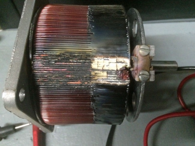
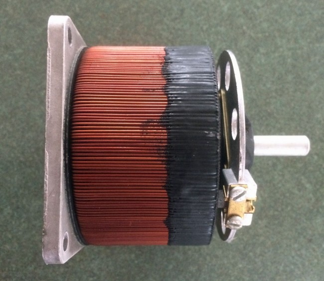
Sadly, there goes support for many Energy Onix and CCA transmitters still in the field. I know of several of those old CCA transmitters that are still cranking away, 40 or more years after they rolled out of the factory in Gloucester, NJ. I have tried, several times, to call Energy Onix since Bernie passed last year and the phone goes unanswered. I wonder if we could pick up the field support and service for these units. I wonder if there are any spare parts left at the old factory building?