WXHC in Homer, New York will never be listed on the NY Stock Exchange. Is that bad?
They don’t think so. A small class A FM station, one of many that signed on in the early 1990s as part of the 80-90 drop-ins (FCC docket 80-90, for those unfamiliar). Many of these stations did not fair too well and ended up being absorbed by larger stations and groups starting with the first wave of ownership deregulation in 1993.
WHXC has remained under the same ownership since it signed on in 1991. Eves Broadcasting is a family operation, employing maybe half a dozen people. Their studios and offices are on the third floor of the Bank of Niagara right in the center of town. The facility is very nice. Like any successful radio station, its focus is the community they serve. The format is “Oldies” but they also broadcast high school football, Syracuse sports and so on. They host a yearly Blue Grass festival on the village green.

The air studio has an Arrakis console and uses BSI Simian automation software. They have live DJs from 6 am to 6 pm, local news, weather, sports, etc.
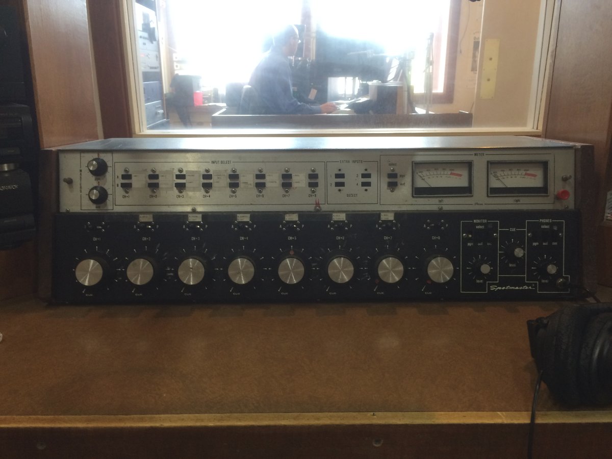
The production room has a BE Spotmaster 8S200A console from 1978. Aside from needing some power supply capacitors, it still works relatively well. However, as the owner’s son said; that thing belongs in a museum.

BE Spotmaster line input card. Probably can still get all these parts if we wanted to.
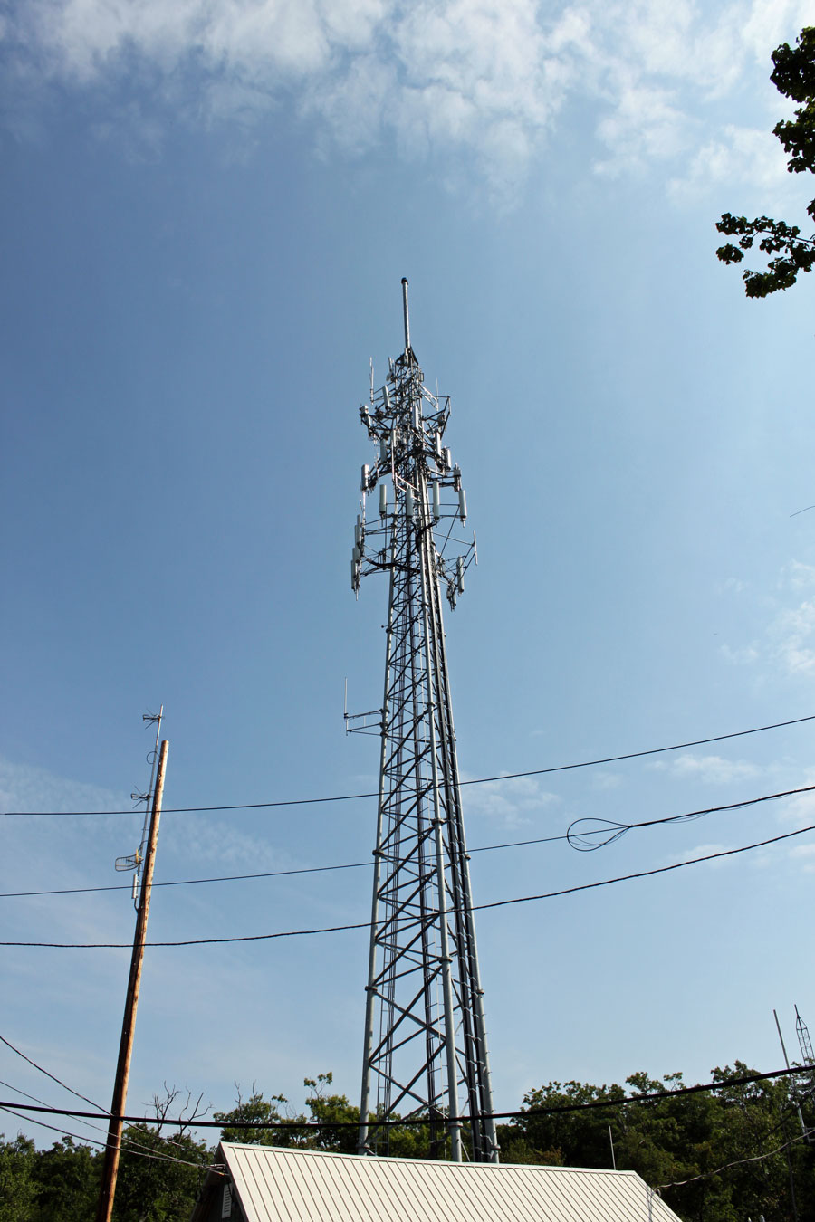
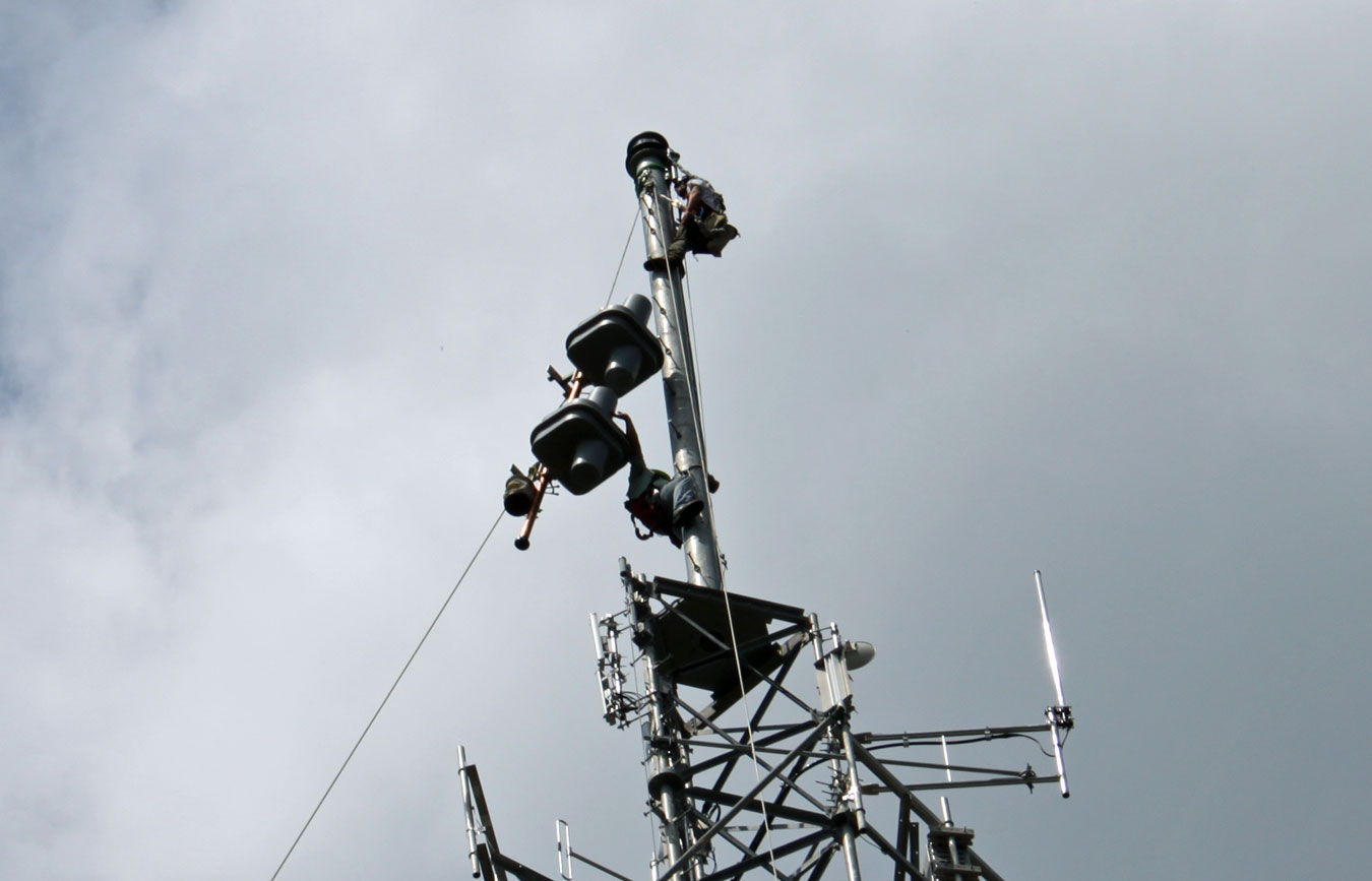
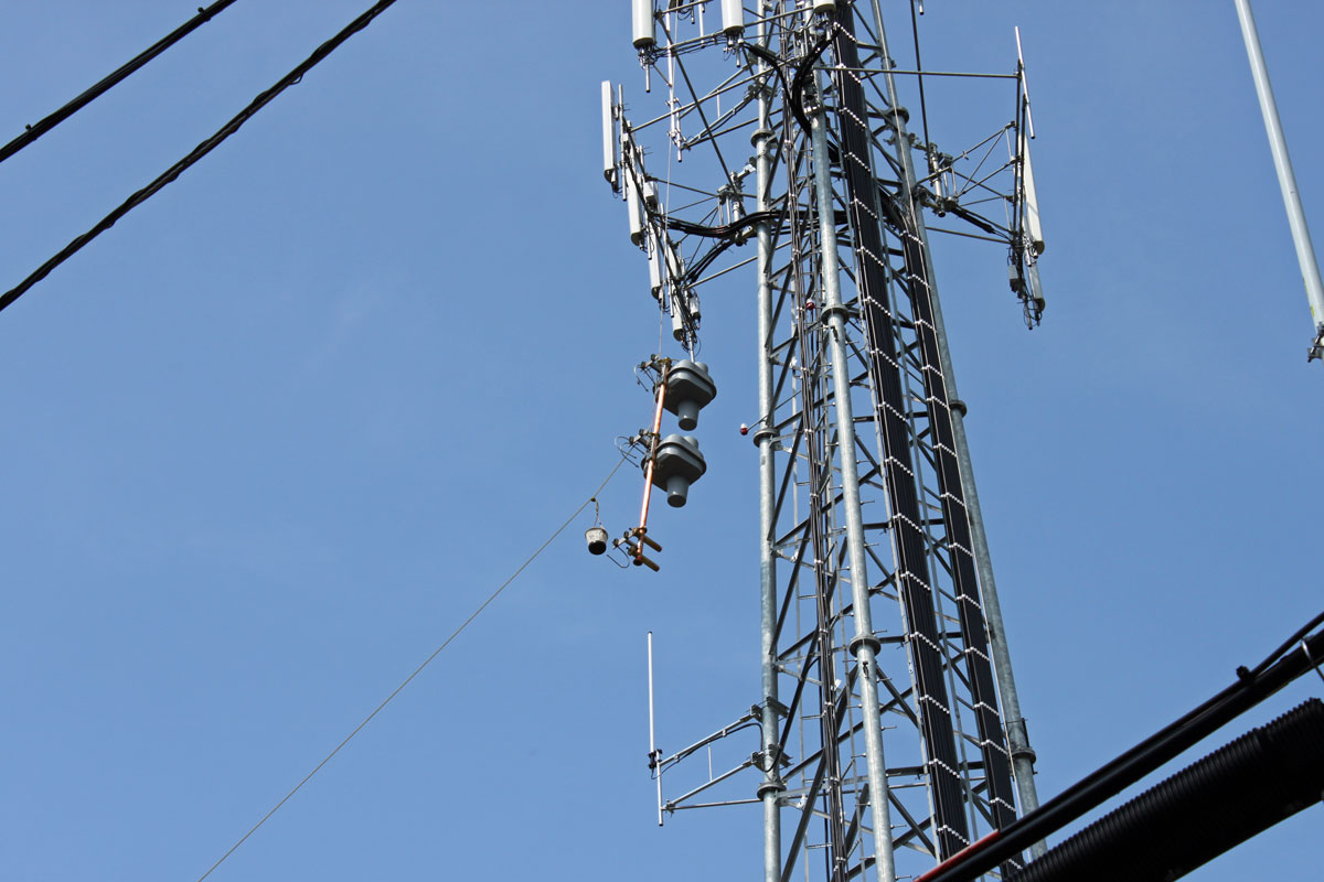
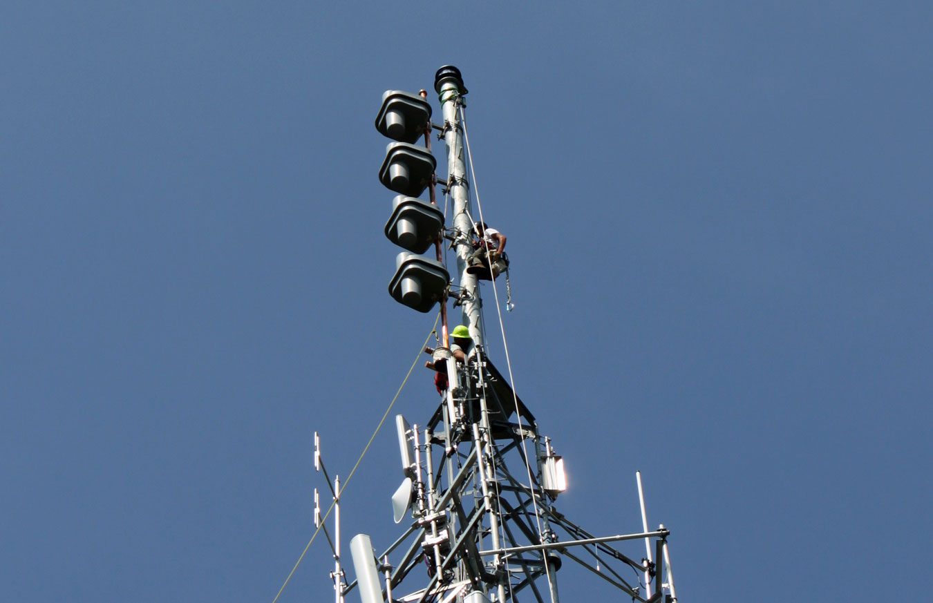
I forgot to take pictures of the transmitter site when I was there. Next time.
We will be working on several projects for these folks, so I will keep you posted on the progress.