I have been working on another formerly directional class B AM station, this one is in Rutland, VT. WSYB has been on the air since 1931 with the same call letters serving the east-central part of Vermont. In 1931, it was operating on 1500 kc with 100 watts of power. In March 1941 it moved to 1490 kc with 250 watts before settling, a few months later, on 1380 with 1,000 watts, directional night time protecting CKPC in Brantford, Ontario, Canada.
The transmitter site was first located at 80 West Street (now known as BUS US 4), in Rutland. It was moved to its current Dorr Drive (Formerly Creek Road) location in 1938, when the station was requesting a power upgrade to 250 watts. Whilst cleaning out the old transmitter building, a copy of an operating log, dated December 7, 1945 was discovered in the attic above the transmitter room:
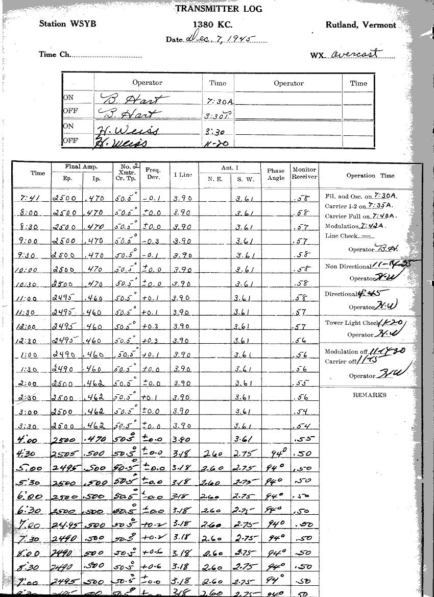
Back from the time when readings were required every 30 minutes.
In 1956, WSYB was allowed 5,000 watts daytime non-directional with 1,000 watts nighttime directional.
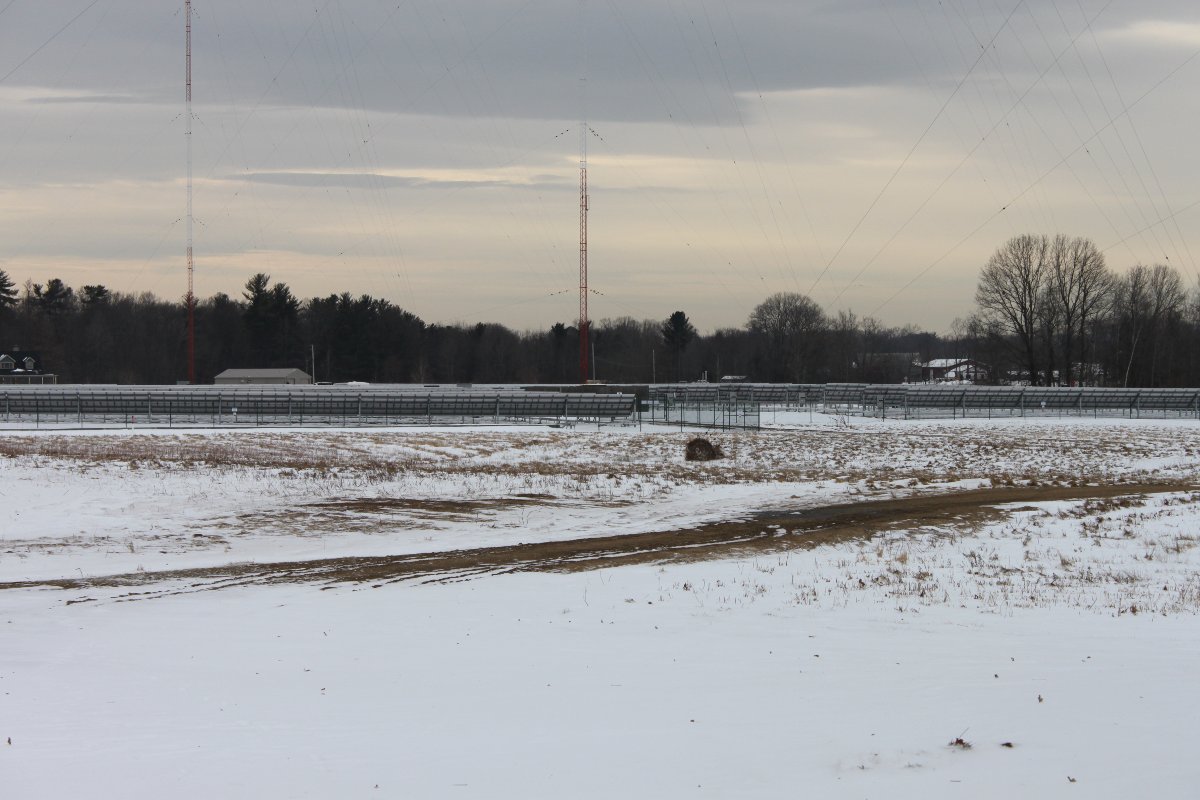
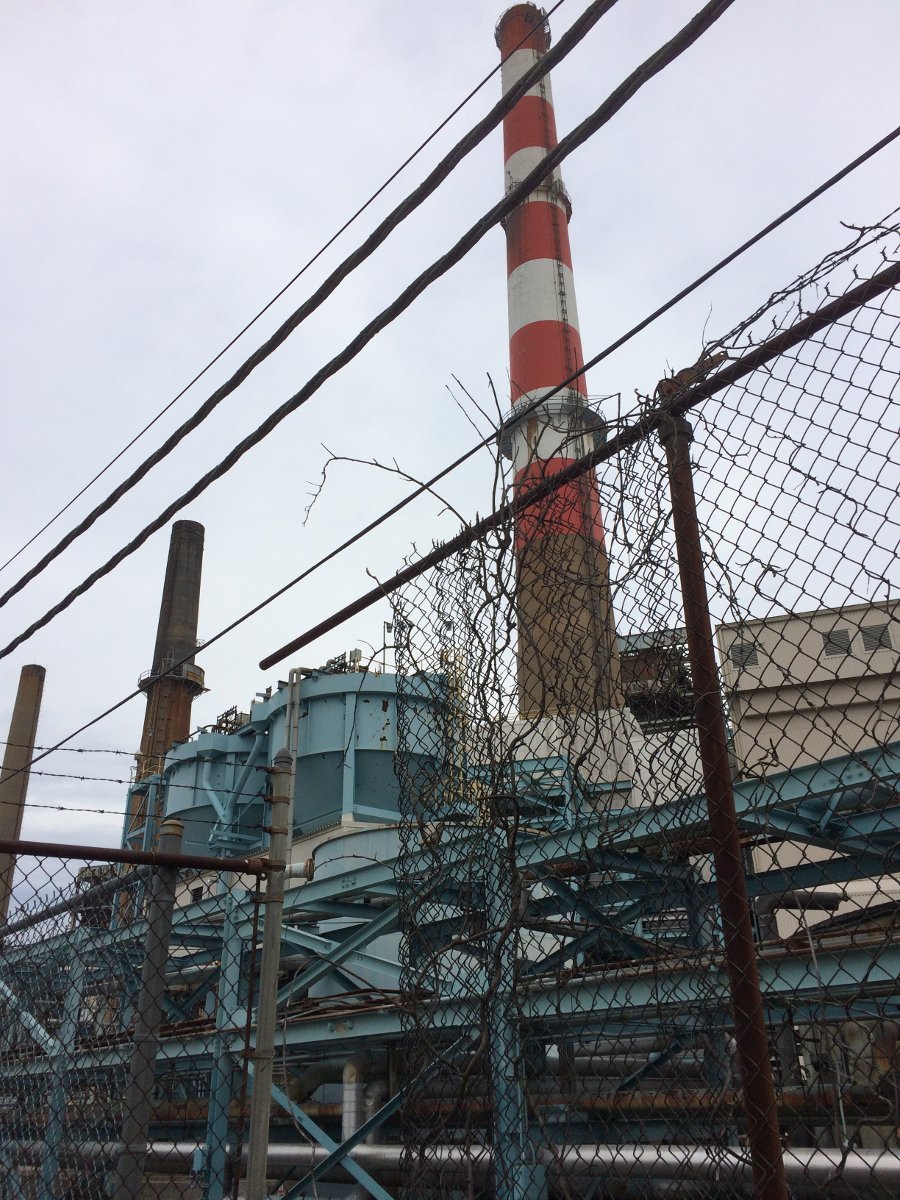
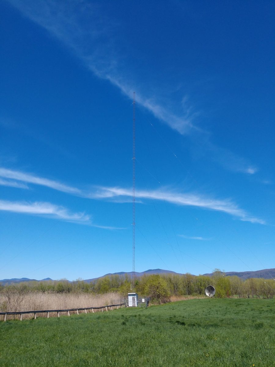
At some point in the early 1990s, the original towers were replaced with solid-leg Pirod towers, each 195 feet tall.
After that, things went the way things do; AM steadily declined in favor of FM, local programming was mostly replaced by syndicated satellite stuff, there were several transfers of ownership, etc.
A translator on 100.1 MHz was added in 2016; the two-bay Shively antenna was installed at the top of the South West tower. There is local programming on the station from 6 am to noon on weekdays. There may also be some gardening shows and other such programming on weekends.
The current owner has decided like they have done in other markets, that AM directional antenna systems are a maintenance nightmare, the risk of FCC sanctions are high for an out-of-tolerance antenna array, and the ratings and income from the station do not justify the risk/cost. Thus, non-directional nighttime operation was applied for and granted. The station is now a Class D with 25 ass-kickin’ nighttime watts.
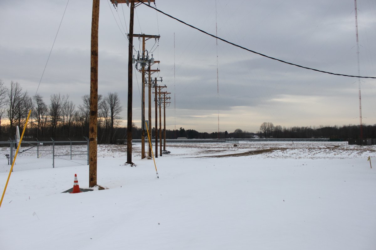
WSYB had a two-tower nighttime antenna system. The tower closest to the building (SW) was also the daytime, non-directional tower and it now holds the FM translator antenna and STL antenna. Thus, it was decided to ground that tower and keep those antennas in service. The far tower (NE), which was the second tower of the nighttime array would become the AM antenna. The nighttime ATU was built for less than 1,000 watts of input power, so several components needed to be upgraded for 5,000-watt operation.
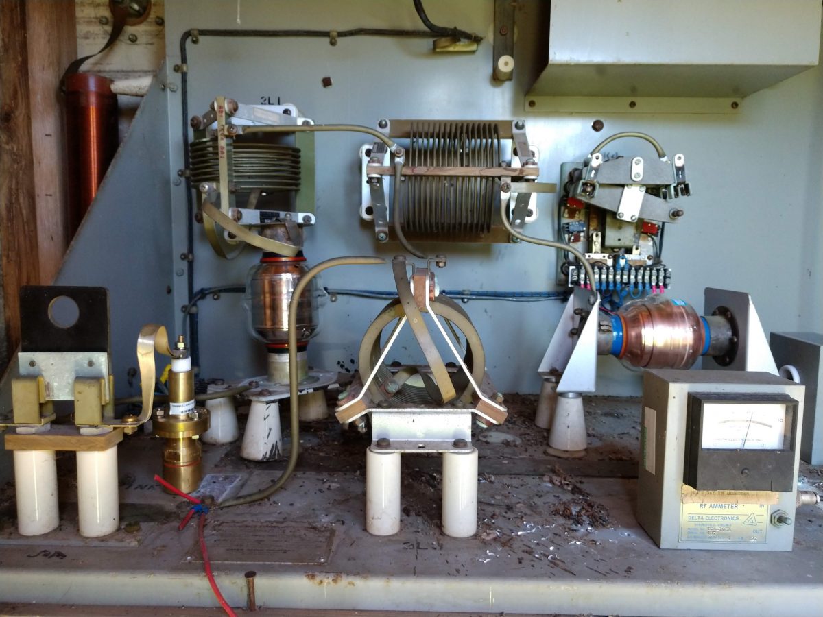
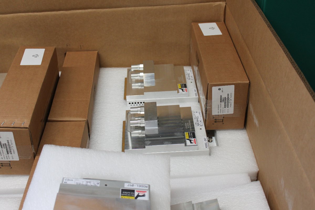
I had available these nice vacuum capacitors that came out of another decommissioned antenna system. The vacuum capacitors are great because the voltage/current ratings are much higher than the mica capacitors that were in the circuit before. You can see black goop where one of the Sangamo mica capacitors on the input leg failed several years ago. These vacuum capacitors are rated at 15 KV and the current rating at 1.38 MHz is probably in the 70-80 amp range. I had to move the base current meter from the former daytime (SW) tower out to the NE tower. The day-night switch was taken out of the circuit. The transmission line to the far tower was replaced with 7/8 inch foam dielectric cable. A slight touch-up of the coil on the input leg of the T network was all that was required to bring it into tune.
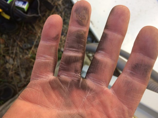
The electric lines to the tower have been temporarily disconnected. As soon as they are reconnected, I will vacuum out all the mouse crap and other debris. The ATU building also needs some work sealing it up against the elements.
The tower base impedance is 75 ohms, +j95 making the base current 8.6 amps daytime and 0.58 amps night time.
For me, the magic of radio exists at that boundary between the real objects (towers and antennas) and the ether. The transference of electrical voltages and currents into the magnetosphere is something that still fascinates me to this day. Coupling a 5,000-watt medium wave transmitter to a tower and watching it work is something that I will never grow tired of.