The name of a song on Pink Floyd’s album, Meddle, released in 1971. The only lyrics in the song are drummer Nick Mason, who says “One of these days I am going to cut you into little pieces.” This was recorded at double speed with Mason speaking in falsetto, then played back at normal speed. Anyway, a good song from one of my favorite Pink Floyd albums.
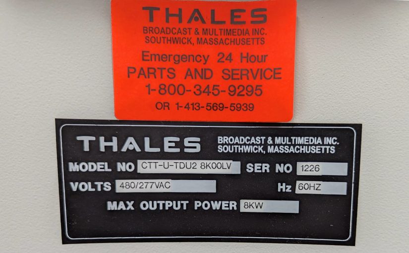
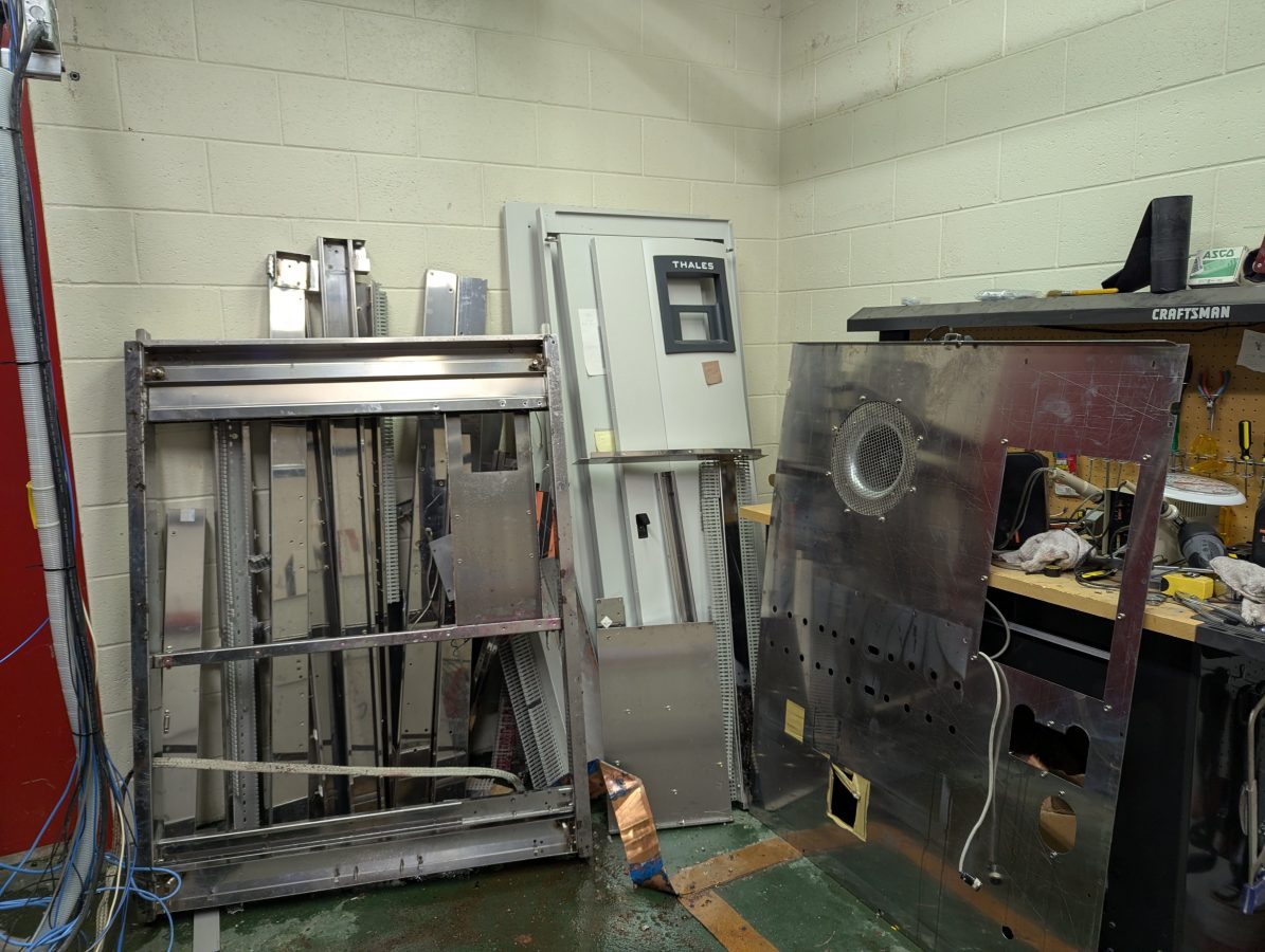
And so it was for this Thales UHF TV transmitter. Installed in 2005 or so during the early transition to digital TV for PBS affiliate WNPI-DT.
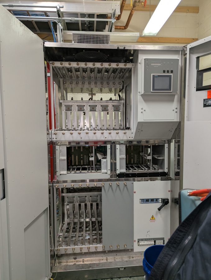
Decommissioning a liquid cooled transmitter requires a few extra steps. First and foremost, as much as possible the antifreeze needs to be captured and collected for proper disposal. In this case, approximately 110 gallons (417 liters) of Dowtherm heat transfer fluid was drained into barrels.
Next, all of the RF modules and power supplies were removed from the transmitter. Both needed to be drained of HTF.
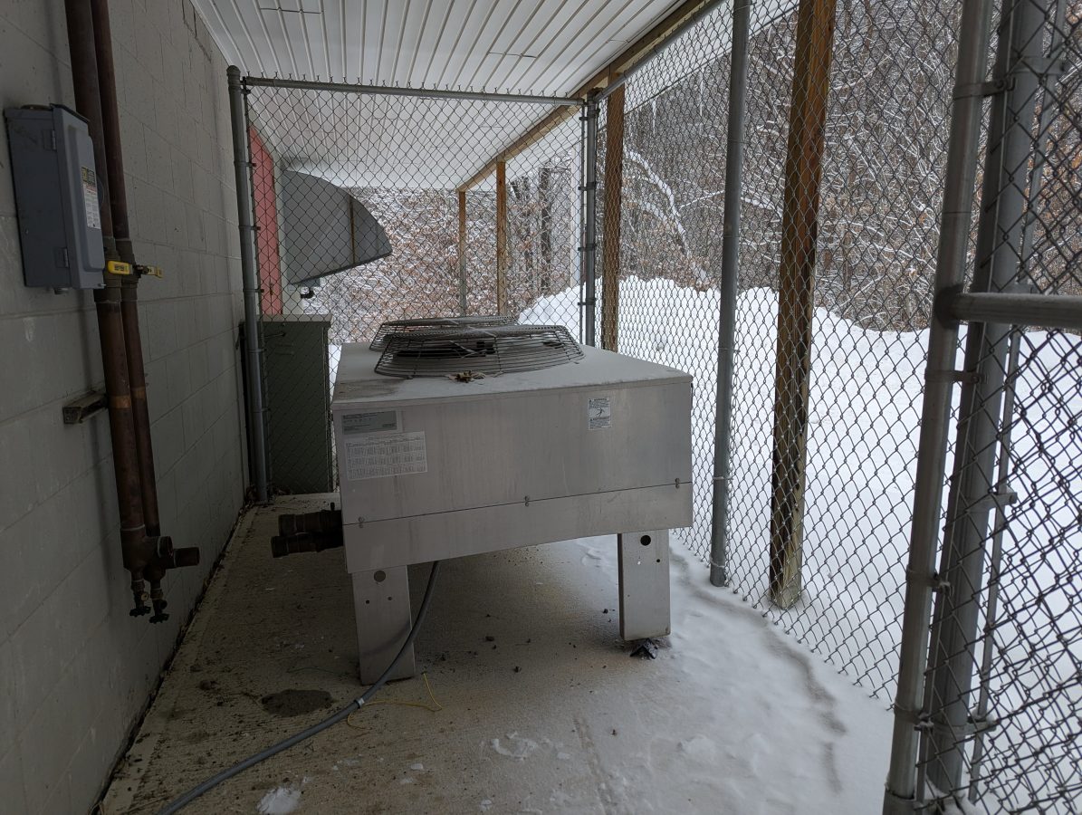
The outdoor heat exchanger presented a new problem:
It was attached to the concrete pad with hammer fixed anchors which needed to be ground off with a hand grinder.
It was a little bit chilly on a 10 F (-12 C) day, laying on the concrete pad, in the snow, under the heat exchanger with a hand grinder grinding the top of of eight little round bolts. After that was done, I managed to pry the legs loose and tip it slightly to get the rest of the HTF out into a bucket. I think the HE had about 15 gallons (57 liters) of HTF.
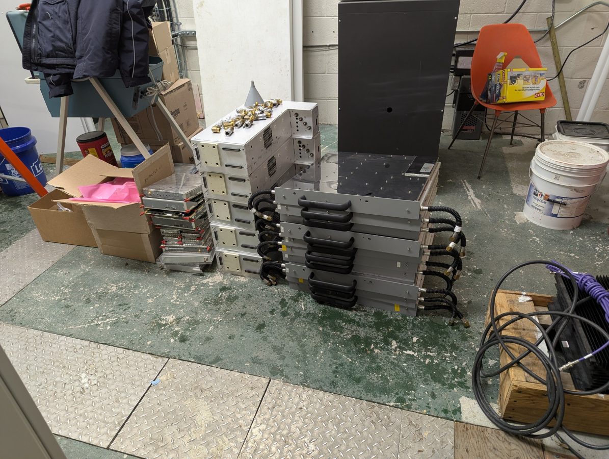
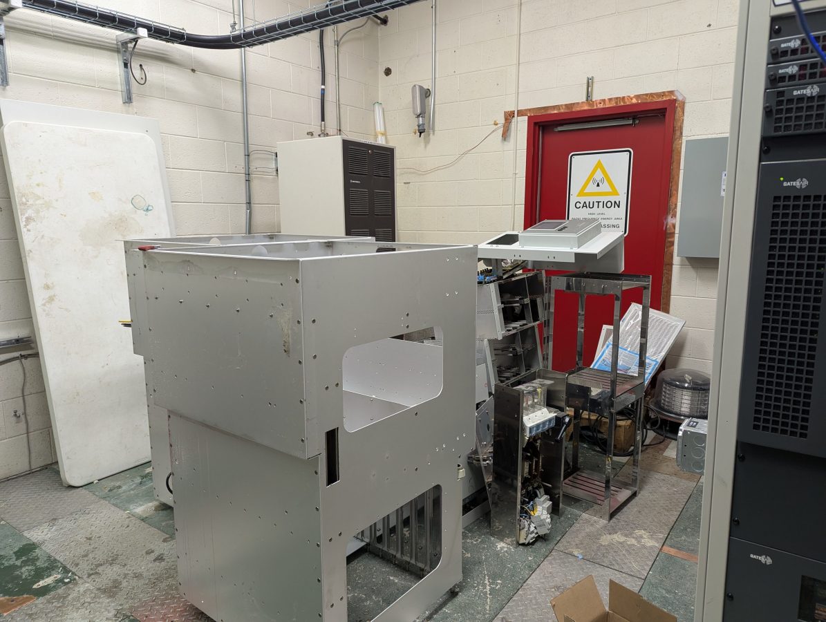
Next, all of the smaller sub assemblies were removed; the upper and lower RF module and power supply frames, the two control module frames, the rails that held the control modules, the AC power input and distribution frame and the controller frame and all the circuit boards. The RF module and power supply frames had HTF tubes and pipes that needed to be drained. The circuit boards are disposed of as E-waste.
The wiring harness was removed.
Finally, the stainless steel main cabinet frame was cut into manageable pieces with the battery powered sawzall (reciprocating saw) so that it could be carried out of the building.
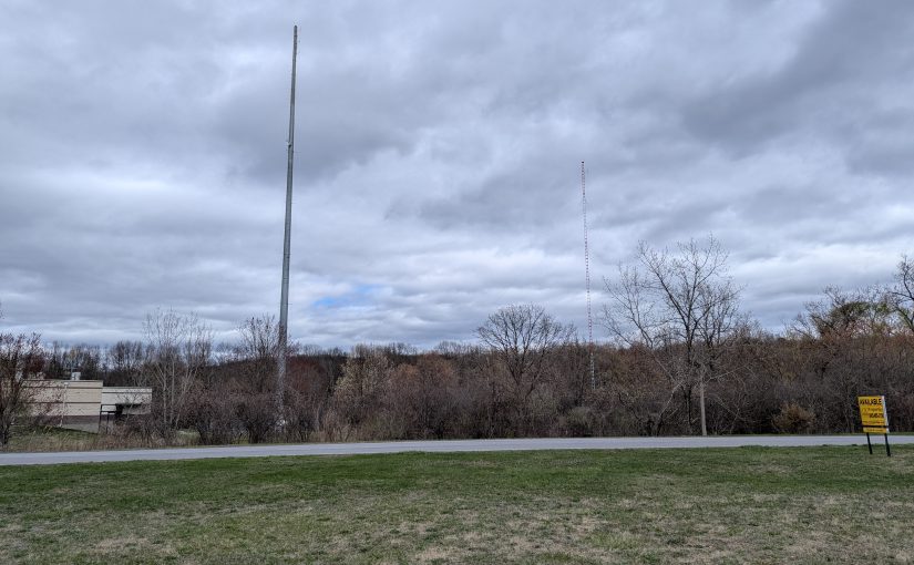
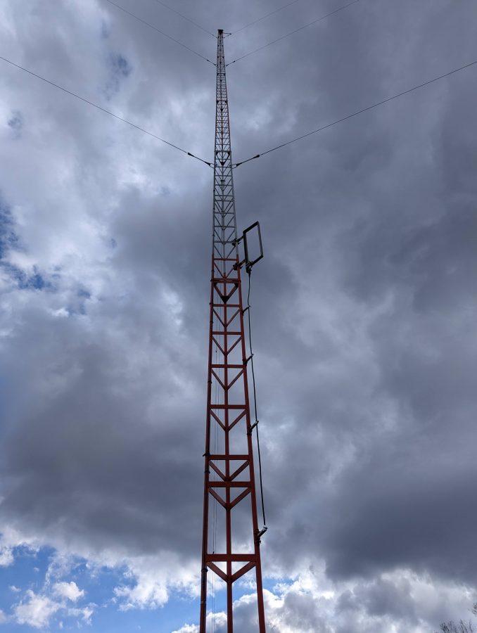
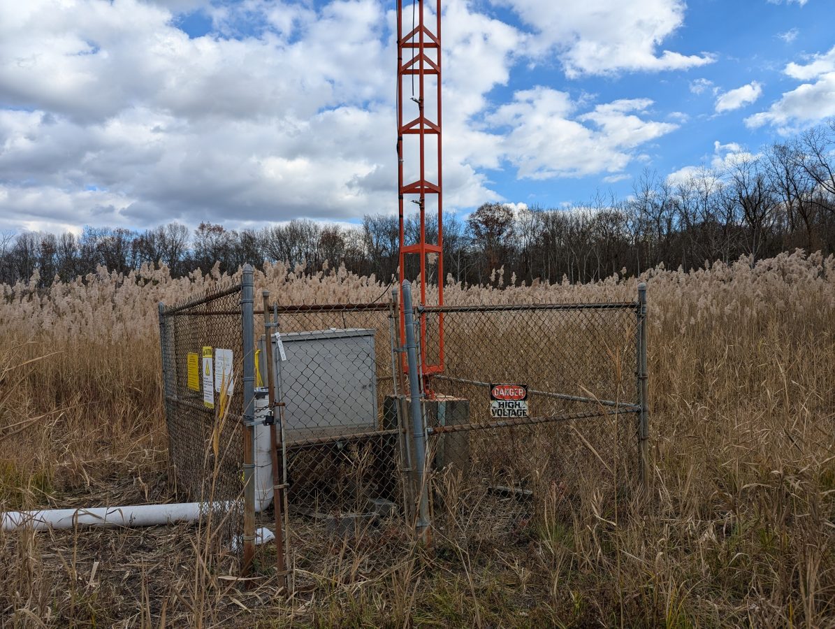
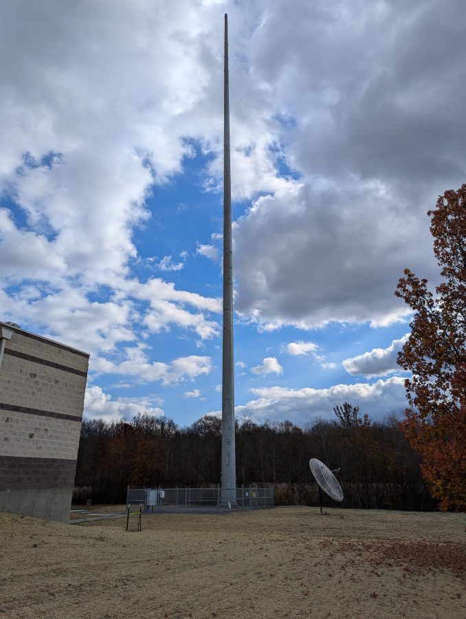
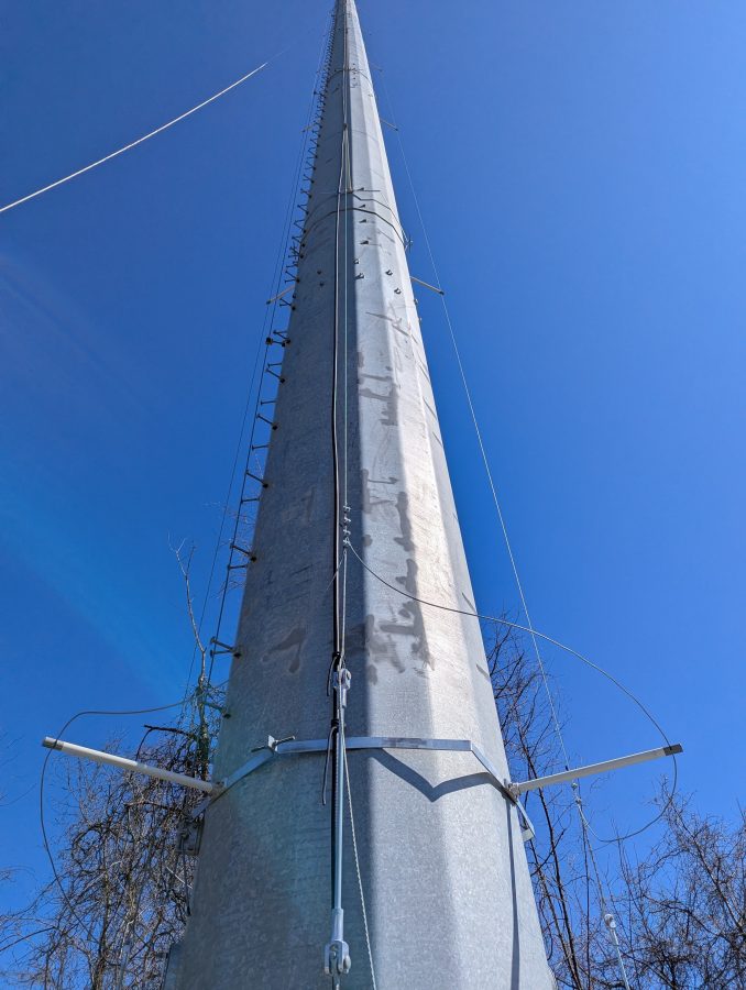
This tower was previously part of a two tower DA. The taller tower was taken down and slowly replaced with a monopole to facilitate vertical real estate development. The shorter tower was retained as the radiator for WKIP-AM, 1,450 kHz, Poughkeepsie, NY.
WKIP tower
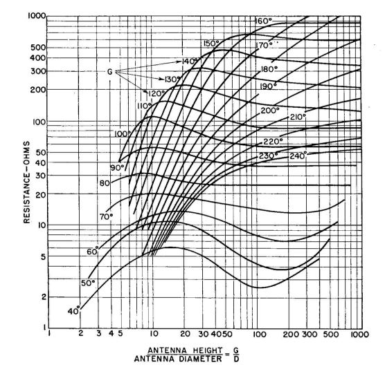
Knowing that the tower is 85 degrees at 1,450,000 Hz, I calculated the height above the base insulator to be 48.816 meters. The tower face is two feet or 0.6096 meters (this becomes important). Using the chart, we can see that the theoretical resistance should be about 25 – 30 ohms:
Height over width, antenna resistance
The bottom or X axis on this graph is the ratio of the antenna height over the antenna diameter or 48.816/0.6096 meters or 80.
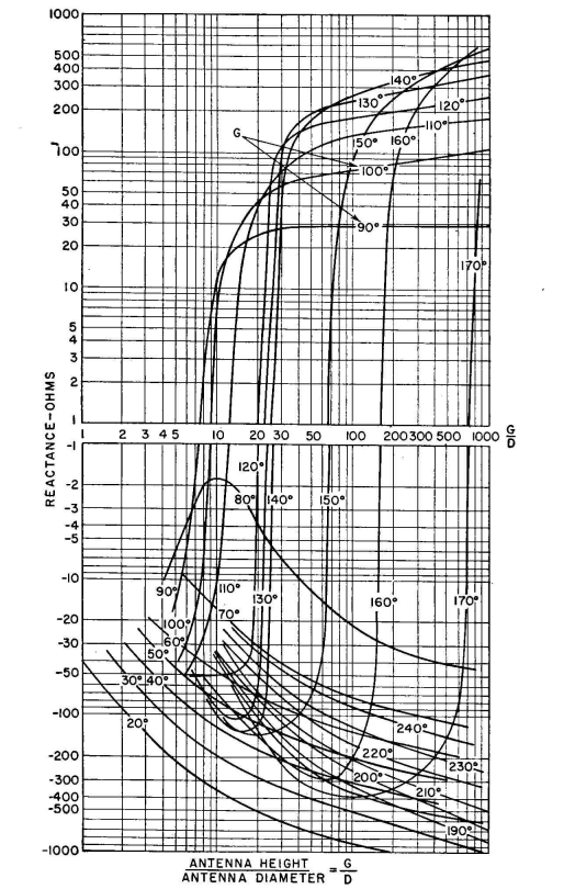
The reactance is slightly less clear according to this chart:
Height over width, antenna reactance
Between 80 and 90 degrees, a large phase shift occurs due to resonance. That means the reactance could be either negative or positive, but will likely be a low number, say +/- 5 ohms. That may be why this height was chosen for the second tower in this system.
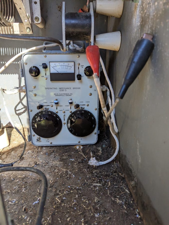
And now for a bit of reality; all of that theoretical information is nice, but a measurement under power is where the rubber meets the road. Using the trusty OIB-3, I obtained a reading of 48 ohms base resistance and +j 37.6 reactance. Thus the base current should be 4.56 amps at 1,000 watts.
OIB-3 base impedance measurement
It was a little tricky setting up the OIB-3. The only place for it was far back in the ATU meaning I had to be careful reaching around active components while getting a reading. That being said, it is only 1,000 watts and in the end, no new RF burns were acquired.
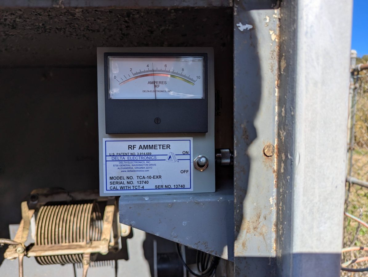
Delta base current meter
The new Delta Electronics base current meter confirms the measured base resistance with the use of Ohm’s Law; I = √(P/R).
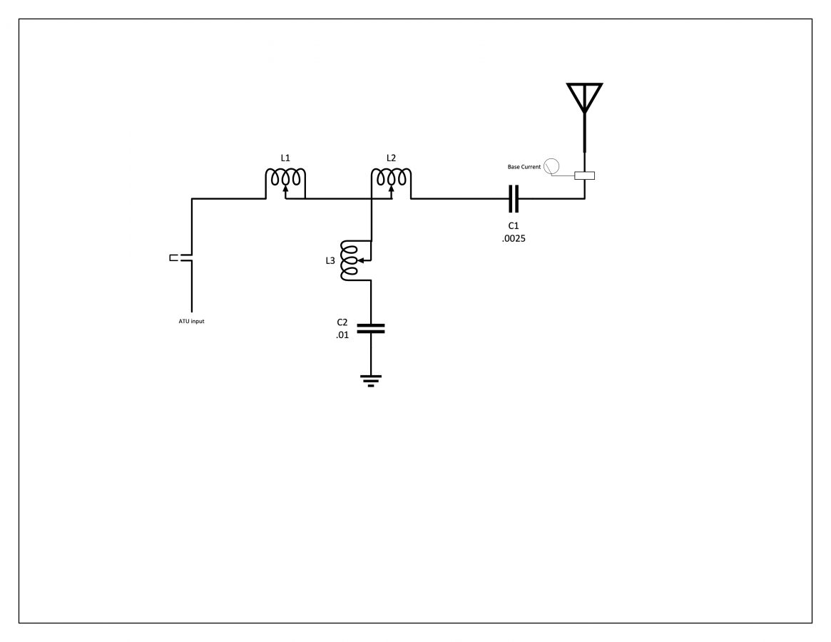
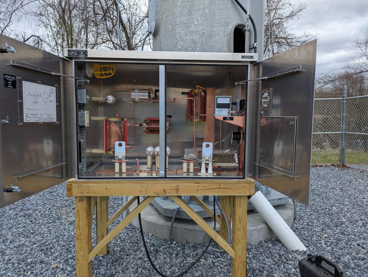
ATU for WKIP tower, circa 1960
The theoretical information is useful for checking the component ratings in the ATU. The series capacitor on the output leg needs to handle the full carrier current plus 125% modulation. I calculate that to be 10.125 amps, so the 12 amp capacitor is sufficient. In the end, the actual base current was about half of the theoretical, so all good. The ATU is a standard T network with a capacitive leg to ground.
WKIP ATU Schematic
While construction was underway both taking down the old tower and putting up the new monopole, the base impedance of the radiator changed several times. Thus, we waited until all of the construction was completed and the monopole was detuned.
Mono Pole, constructedDetuning skirt installedATU and detuning network for monopole
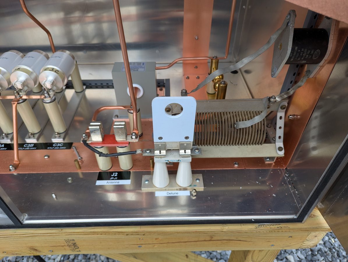
The skirt wires on the monopole are doing double duty. They are first, detuning for the AM tower located about 57 meters (186 feet) away. Next, they are a backup antenna system in case that main tower becomes unusable. This can happen from time to time as the swamp floods or if any type of tower work is needed. To do that I installed another J plug with the detuning network, which will be the normal position. To switch to antenna, it is moved to the antenna position. The base current meter is on the output leg, so it can be used to detune the monopole or measure the station output power.
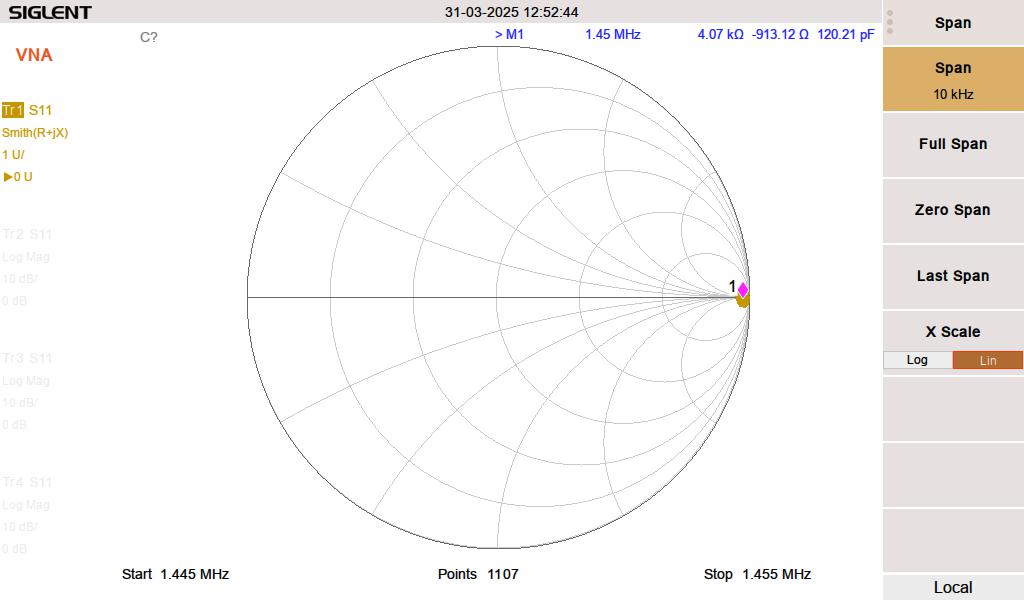
Monopole in detune mode
I used the analyzer to get the detuning network close to resonant. The second step involved using the base current meter to touch up the tuning with the transmitter running into the tower 57 meters (186 feet) away. This is necessary because the two structures are close together. The skirt wires on the monopole pick up a lot of RF, therefore the stray capacitance on the inductor coil plays a role in the circuit. The net result is less inductance is needed when the transmitter is on. The resonance point will shift somewhat with ground conditions, but as long as the monopole impedance is high (above say 2K ohms) the structure should be invisible to the nearby 1,450 KHz radiator.
Monopole detuned for 1,450 kHz; impedance is 4.07 K ohms, at or close to resonance
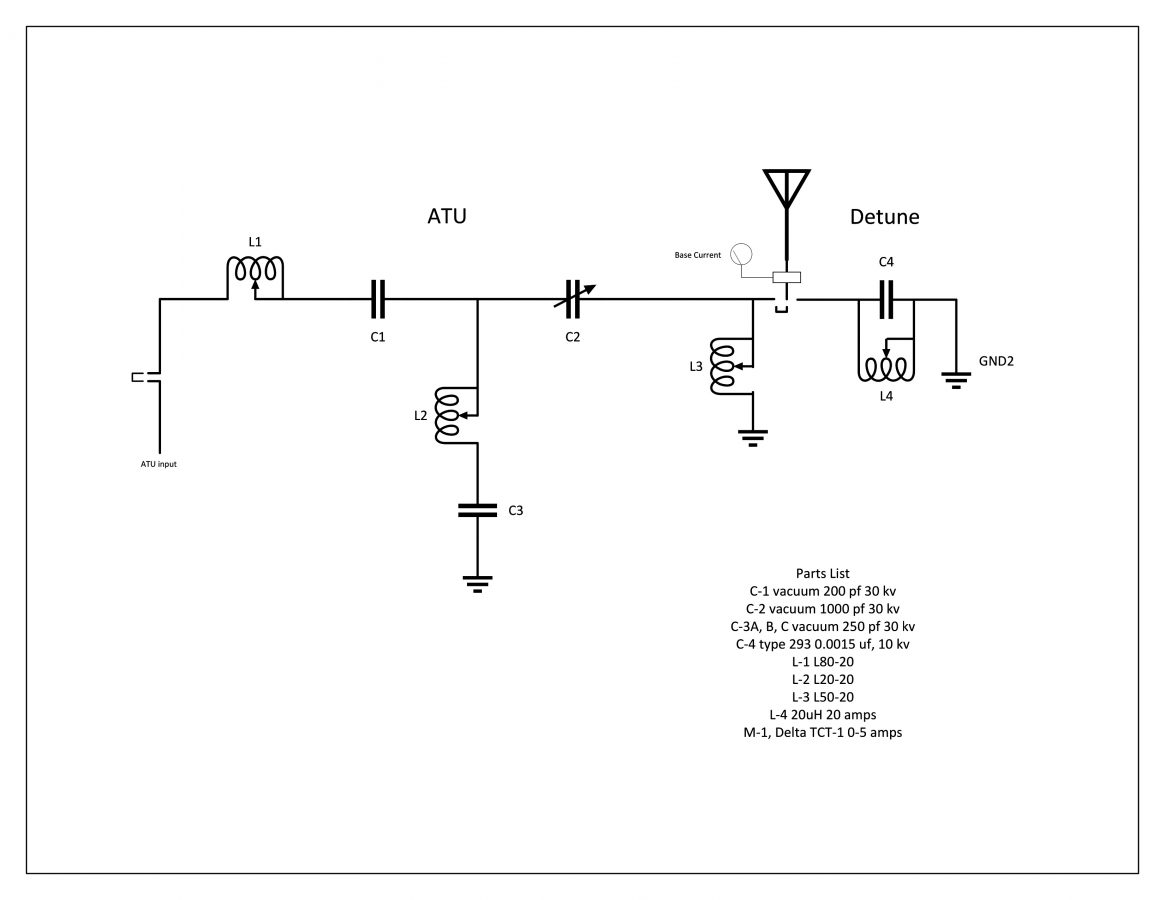
The ATU for the monopole looks like this:
The operating impedance measurement shows a 47 ohm impedance, making the daytime base current 4.61 amps. It is coincidental that the two tower impedances are that close.
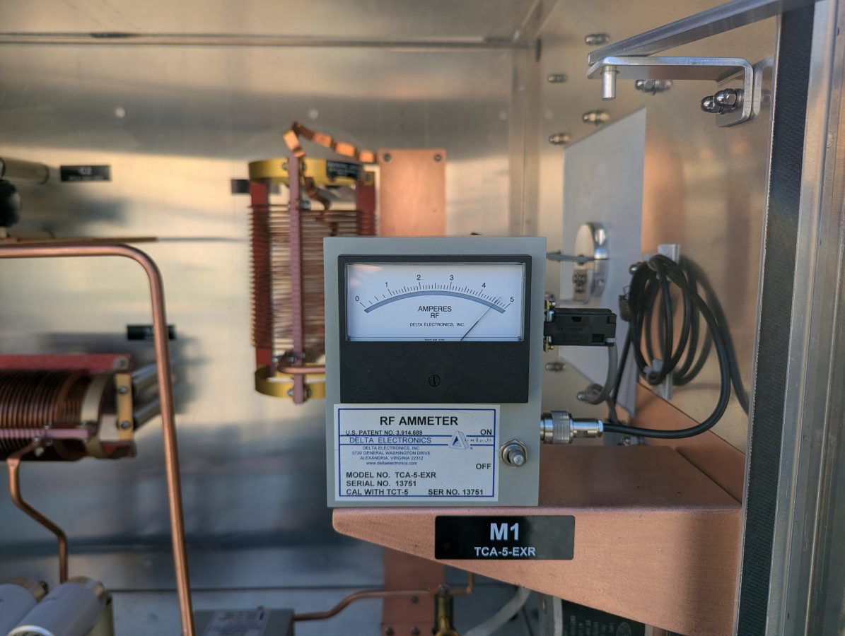
Aux tower base current meter
The new base current meter agrees with the impedance measurement.
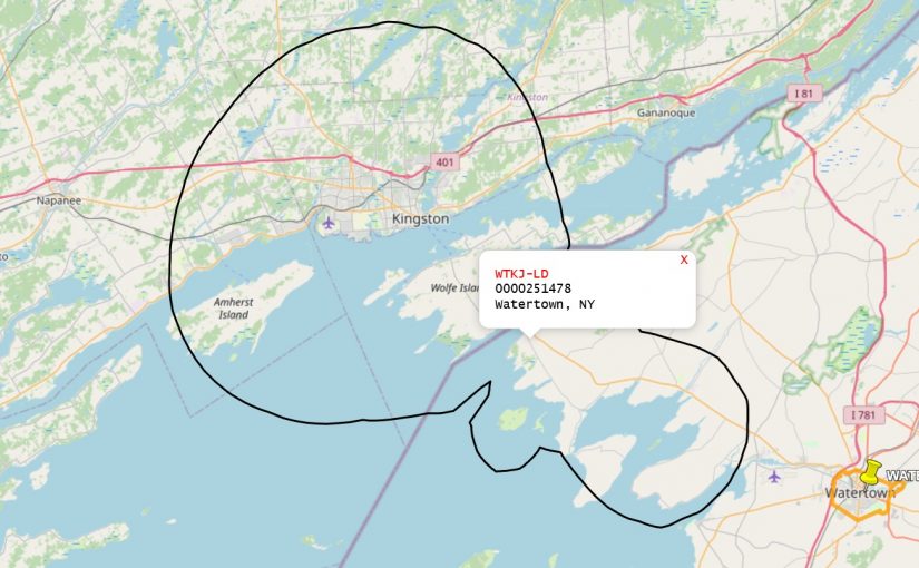
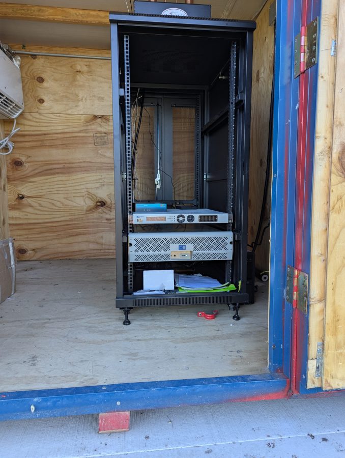
Installing another couple of these stations recently in the New York/Canadian border region. In this case, WTKJ-LD now transmitting from Cape Vincent, NY. This is owned by Sagamore Hill broadcasting and is retransmitting the NBC affiliate from Watertown, NY.
This is a pretty simple set up; BE 600 Watt UHF TV transmitter, Pro Television Exciter, 6 pole Dielectric Filter, and an 5 panel UHF antenna.
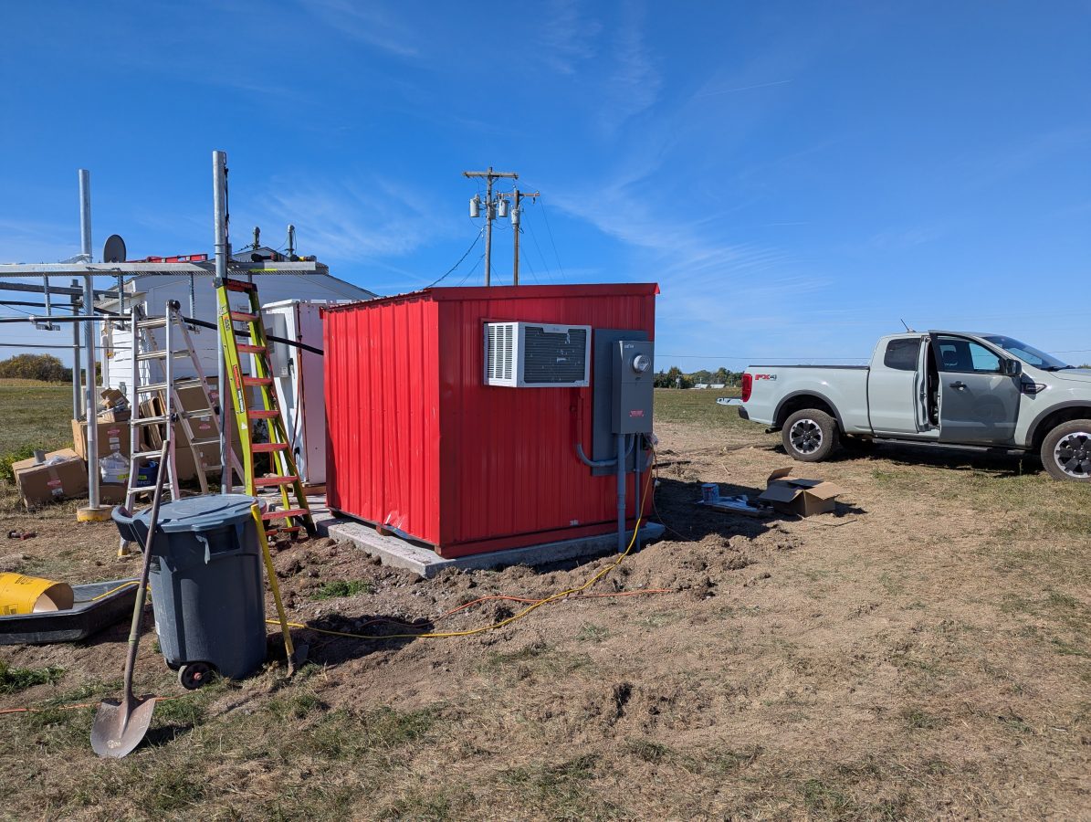
The shelter was made by Broadcast Electronics, it is somewhat small, but serviceable.
The LG window unit works well enough to keep the shelter cool. The transmitter runs at about 35% efficiency. The TPO is 470 watts, thus the transmitter puts out about 300 watts of heat into the room continuously.
The local cord cutters can get the following channels:
19.1
1080i
DD5.1
WVNC-NBC
19-2
480i (w)
DD2.0
Antenna TV
19-3
480i (w)
DD2.0
ION
19-4
480p (w)
DD2.0
Grit
19-5
480p (w)
DD2.0
Bounce TV
19-6
480p (w)
DD2.0
Court TV
19-7
480i (w)
DD2.0
QVC
19-8
480i (w)
DD2.0
SonLife
The weather up here is great! Cape Vincent is a nice small village with some decent local businesses. Unfortunately, summer is their main focus and many of them have closed down for the season. Still, there is a decent cup of coffee and the local market has a deli section that makes good sandwiches.
The ability to do a Distance to Fault Measurement can greatly speed up the troubleshooting of potential antenna and/or transmission line problems. DTF measurements take on one of two forms; Time Domain Reflectometry (TDR) and Frequency Domain Reflectrometry (FDR).
TDR is the traditional method of measuring Distance to Fault. The test equipment sends short DC pulses down the cable and measures any return loss or SWR. Energy reflected back toward the instrument will plotted based on the time difference between the transmitted signal and the received reflection, similar to RADAR. This works well finding opens or shorts, but may not see lesser faults that could still be causing problems.
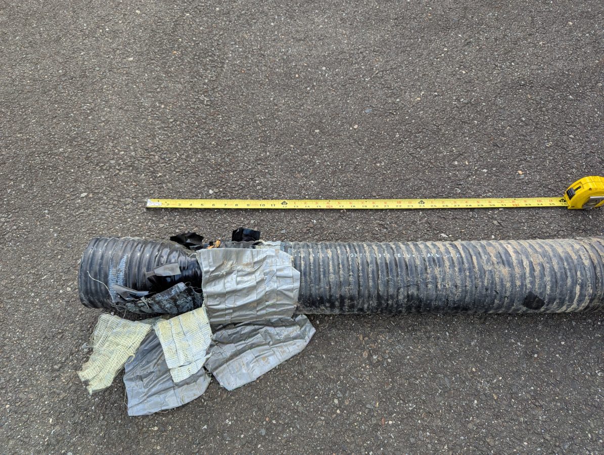
Damaged six inch coax
FDR is now common in most field models of Vector Network Analyzers. An FDR sends a frequency sweep down the cable then uses an Inverse Fast Fourier Transform (FFT) function to convert the information into a time domain. FDR can more reliably detect smaller issues with cables such as kinks, sharp bends, water in the cable, poorly applied connectors, or bullet holes. The piece of dented cable above would not have given a large reflection on a TDR, but on an FDR it would show up very nicely.
Like a VNA, an FDR needs to be calibrated for the sweep frequencies in use. The frequency span or bandwidth of an FDR has a major role in DTF measurements. A wider span will result in more precise fault information, however, it will reduce the over all length that the instrument can test. For most broadcast RF applications, cable lengths are less than 670 meters (2200 feet). Many instruments will adjust the maximum distance automatically based on the chosen span and velocity factor.
For my equipment, a Siglent SVA 1032X, the maximum distance for any frequency span can be found with this formula:
Maximum Distance (meters) = 7.86 x 10⁴ x Velocity Factor/Span (MHz)
Thus, to get best resolution sweeping a cable that is 670 meters long with a velocity factor of 86%: 7.68 x 10,000 x .86 / 95 MHz = 695 Meters maximum distance.
The resolution for any frequency span can be calculated with the following formula:
In this case, the resolution would be +/- 1.35 meters. For shorter cable lengths a larger span can be used for better resolution.
My preference is to center the sweep frequency around the channel or frequency of the system under test.
To use a DTF function, a few inputs are needed:
The velocity factor of the transmission line
Cable attenuation for the swept frequency in dB/Meter
The approximate length of the line under test
The cable velocity factor and attenuation can be obtained from the manufacturer’s data sheet. Keep in mind that the manufacturer’s data is an estimation. These are usually pretty close to the actual number, but may vary due to tight bends in the cable, any splices, transitions to different cable, etc.
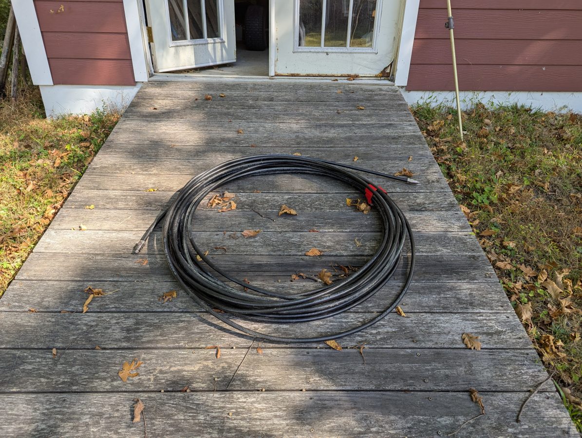
Cable to test
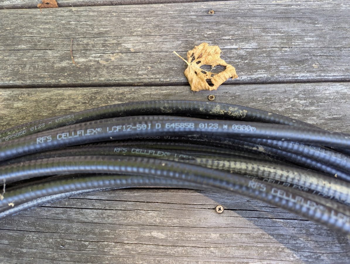
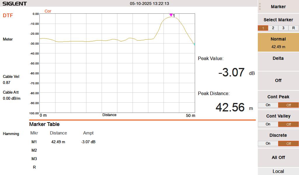
I had this used 1/2 inch RFS LCF12 50J cable in the barn, left over from project. Fortunately this is newer cable and it had the length marked out in meters. The beginning number was 0980 meters, the end was 1021 meters. Each meter marking has an asterisk before the number. I used a meter stick to measure out the distance between the asterisks and they are exactly one meter apart. I then measured the distance between the asterisk and the connector on each and ended up with 1.49 meters (4.9 feet) additional length, making the total length 42.49 meters (139.4 feet). The manufacture’s specification on velocity factor is 0.87 or 87% of the speed of light.
Manufacture’s markings
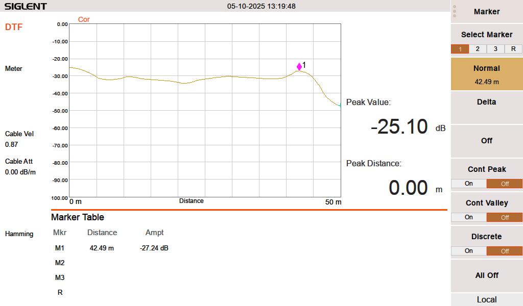
When I test this line with a 50 termination, it looks like this:
FDR DTF, 50 ohm termination at 42.49 meters
When I test the line either open or shorted, it looks like this:
FDR DTF, cable shorted at 42.49 meters
I swept the cable at HF frequencies (3-30 MHz) since I think that is what this is going to be used for. At 3 MHz, the cable has a loss of approximately 0.003 dB per meter, which is inconsequential for this test. The velocity factor of 0.87 is pretty close. A longer run might indicate that it is actually 0.875 or 0.88.
Velocity factor and cable impedance are very important when using the Moment of Methods (MOM) system for AM antenna work. In that situation, both need to be obtained with a VNA for the FCC application.
The best practice is to sweep into a terminated line. In an AM system, a termination can most often be applied at the ATU input J plug. Sweeping into an antenna is possible, however there are several things that may lead to poor results. Most often, an FM antenna will look like a short on a DTF measurement. A UHF slot antenna will look open. In addition to that, the DTF measurement may be corrupted by any signals being received by the antenna while the system is under test.