I am a strong proponent of non-computer-based air chain processors. Something about listening to dead air while the computer reboots is annoying and every computer needs to be rebooted every now and again.
All of that being said, I recently had a chance to play around with Breakaway Broadcast audio processing software. I have to say, as a low-cost, very versatile platform, it can not be beaten. I would put it up against any of the high-end FM audio processing, provided one uses a high-quality sound card with an adequate sample rate.
Claesson Edwards Audio has developed several software-based audio processors for a variety of end uses. They make several recommendations for hardware and operating systems, Pentium 4 3.2 GHz or better, dual-core preferred. If one is interested in using the sound card to generate composite audio, then any sound card capable of a true 192 KHz sample rate will work. They list several that have been successfully tested on their website.
For approximately $1,200 dollars or so, one could buy a decent computer, the Breakaway Broadcast software, and the Airomate RDS generator software. For a Mom and Pop, LP, or community radio station that is looking to do some high-end audio processing and or RDS, that is a good deal. I would add a UPS to the computer and keep backup copies of the software installed on an emergency computer just in case. One can never be too safe when it comes to computers, viruses, hackers, and other malicious persons.
Things that I like
Inexpensive, the fully licensed version is $200.00. The demo version is free but there is a 30-second promo every thirty minutes.
There are several factory presets, but everything is fully configurable, changes can be named and saved allowing some experimentation.
Audio cards with 192 KHz sample rate or greater can be used to generate composite audio, eliminating the need for a separate stereo generator
RDS capable with additional software (Airomate2, approximate cost $35.00)
The same processing computer can be used for streaming audio and or AM audio processing simultaneously.
A full set of audio calibration tools for AM and FM transmitters allows correction for tilt, overshoot, and linearity. Can add pre-emphasis at any user-selectable rate.
Fully adjustable phase rotators.
Things that I don’t generally like:
A computer-based system using Windoze operating system
WXPK in White Plains, NY has been using this software to process their streaming audio for about 2 years now. The software itself is extremely stable running on a stand-alone Windows box with XP service pack 2.
It is that time of the year again, at least in the northern hemisphere, for thunderstorms. I am a big proponent of grounding everything, there is simply no such thing as too much grounding. I took a course when I was in the military given by Polyphaser in which grounding for lightning protection and EMP was emphasized. It was very interesting in several respects.
One commonly held belief is that when lightning strikes an object, the ground immediately absorbs all of the charge. That is not true in most cases due to ground resistance. Eventually, the ground will absorb the charge but it can take several seconds to do this, especially with a big strike. Equipment is damaged by current flow, therefore, every effort must be made to keep all of the equipment at the same potential, even if that potential is 10KV. That is where a single-point ground bus comes in. Bonding every piece of equipment to a common ground bus ensures that no one device is at a lower potential while the charge dissipation is occurring.
The second misunderstanding about lightning is that it is DC voltage. That is true, however, a lightning strike has an extremely fast rise time, on the order of 30 microseconds. That makes it behave more like an AC voltage of around 10 KHz. Therefore, ground bus wires need to have a minimum inductance. Solid #2 wire is best, keeping it as straight as possible and using long sweeping turns where needed. All bonds should be exothermically welded (CAD weld).
The ground system was installed at WKZY, WHHZ, and WDVH-FM transmitter site in Trenton, Florida. Central Florida is the lightning capital of the US. Prior to doing this work, the Harris FM25K transmitter was knocked off the air at least once a month. Since this was installed in 2005, they have had zero lightning-related damage. The ground rods are 20 feet long, driven down into the water table, spaced 20-30 feet apart.
All coax shields and metal conduits that come into the building should be bonded to the ground system where they leave the tower and where they enter the building. At most tower sites, I install a ground ring around the outside of the building with rods every 20 feet or so. From that ring, 5 to 6 radials outward 40 feet with ground rods every twenty feet works well. I also install 5 to 6 radial out from the tower base with the same configuration. The tower and building grounds are bonded together. This is important because when the tower gets hit, the ground will quickly become electrically saturated. If the building and the equipment inside are at a different potential, current will begin to flow toward the lower potential, thus damaging gear.
All Coax, control, and AC cables in and out of sensitive equipment should have ferrite toroids on them. Transmitter manufacturers normally supply these with new solid-state transmitters, as MOSFETs are particularly sensitive to lightning damage.
This is a Potomac Instruments AM-19 directional antenna monitor. It was damaged by a lightning strike two weeks ago on the WBNR tower in Beacon, NY. The case arced to the rack it was mounted in. This was a large strike, as several components in the phasor control circuit were also damaged. The fact that this arced means that somehow the sample lines are not attached to the single-point ground for this site, which needs to be corrected.
Insulated AM towers present special design problems when it comes to lightning protection. Generally speaking, tower arc gaps should be set so there is side by side and there is no arcing on positive modulation peaks. Depending on power levels, this can be anywhere from 1/2 inch to 2 inches. Tower impedance also plays a role in setting arc gaps. The final link between the ATU and the tower should have several turns in it. The idea is to make that path a higher impedance path for the lightning, causing it to dissipate through the arc gaps. Incoming transmission lines from the towers should be bonded to a copper bus bar at the entrance to the building. All of this grounding needs to be tied to the RF ground at the base of the tower.
Arial phone cables can act like large lightning antennas for strokes several miles away. It is very important that the cable shield and the cable termination device are bonded to the building ground buss. I have seen installations where the TELCO tech pounds in a separate ground rod outside and connects the TELCO equipment to that. That defeats the concept of single-point grounds and should be fixed ASAP.
Electrical services entrances also can act like big lightning antennas. Normally, pole-mounted transformers will filter some of this energy out. Internal electrical distribution systems can also add impedance, and thus act as inadvertent filters for lightning. In most mountaintop transmitter sites, however, some type of power line surge protection is needed.
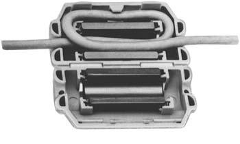
Inside view of LEA surge suppressor
There are two types, series, and parallel. Parallel types are the least expensive and least intensive to install. They are usually found mounted next to or on the service panel and fed with their own breakers. They usually have some type of MOV or similar device that acts as a crowbar across the AC mains, conducting spikes to the ground. Series types go in between the service entrance and the main panel. They include a large inductor designed to force spikes off into shunts. A series-type protector offers more complete protection than a parallel.
I read a very good and interesting post on James Critland’s blog. He is somewhat concerned about the trend for mobile wireless providers to no longer offer unlimited data service for a flat fee. I find it interesting that all of these companies seemed to have reached the same conclusions at the same time. But anyway…
The general surmise of James’ post is that the average person will not be able to afford online radio through a 3 or 4G device because of the limited minutes available and the additional charges incurred. (35 quid is about $50.00) To make that meaningful to a US audience, I decided to redo some of James’ math.
Iphones are primarily serviced through ATT. ATT has two different data plans that are coupled with voice plans in a bundle. For example, a 450-minute voice plan and a 200 Mb data plan will cost $55.00. A 900-minute voice plan with a 2 Gb data plan will run $85.00.
Here are a few interesting tidbits and some good math:
A 64 kbps stream runs 7.68 kb per second, or 460 kb per minute (1 kilobit per second = 0.12-kilobytes)
1 hour of online listening equals 27,640 k bytes of data transferred
The 200 Mb plan cost $15.00 with voice plan, the 2 Gb plan cost $25.00 with voice plan
The 200 Mb plan would allow for 7 hours of listening time if no other data use occurred
The 2 Gb plan would allow for 72 hours of listening time if no other data use occurred
Beyond those data transfer amounts, extra charges are incurred
Almost 50% of the time spent listening to all radio sources (terrestrial, satellite, online) is in the car. The average person in the US listens to the radio for about 3 hours per day or 90 hours per month. Half of that time would be 45 hours or so.
Clearly, anyone who is more than a casual listener of online radio will need the 2 Gb plan. However, given the paucity of entertainment available from traditional radio sources, this is not an outlandish amount to pay. I remember in the ’70s when folks were saying cable TV would never catch on.
Blanketing interference refers to the phenomenon of receiving radio signals on devices not designed to do so. In broadcast radio, this is defined for AM stations in part 73.88 as:
The licensee of each broadcast station is required to satisfy all reasonable complaints of blanketing interference within the 1 V/m contour.
And for FM stations, it is part 73.318:
Areas adjacent to the transmitting antenna that receive a signal with a strength of 115 dBu (562 mV/m) or greater will be assumed to be blanketed.
Any interference to any device with that signal contour is blanketing interference. 73.318 further states that:
permittees or licensees who either (1) commence program tests, or (2) replace their antennas, or (3) request facilities modifications and are issued a new construction permit must satisfy all complaints of blanketing interference which are received by the station during a one year period.
I have always taken a more pragmatic approach to interference complaints. Rather than pass the buck and tell the homeowner or business owner that it is not our (the radio station’s) problem, I’d go and try to help them out. Generally speaking, the interference problems are close to the transmitter site, so on the next trip to that site, I would bring RFI filters and my 25 years of RF experience and solve the problem. I would like to think this helps the station’s and the company’s image in the community.
Most of the problems are pretty easily solved, although once in a while, I have come on some head-scratchers. An AM station playing on the outlets in a guy’s garage, the mic cords on a church PA system, and an off switch on a blender, off all things. The Bare Naked Ladies had a line in the song Light up my Yard: “we can dance to the radio station that plays in our teeth.”
What I have found is to start with the simple stuff first, check the ground on the electrical service entrance panel. One might be surprised to find it disconnected, corroded, or missing completely. On more than one occasion, I fixed all of the RFI problems with a simple turn of the screw holding the ground wire to the grounding electrode. In my experience, this is the most common single failure point. A disconnected ground will cause the entire neutral wiring system to act like a giant AM antenna, with all sorts of bad outcomes.
RFI suppression ferrite
Most often, telephone answering machines, cordless phones, and other devices powered by wall warts are suspect. Those devices do not have a path to ground. A few turns of all the wires coming and going from said device around a ferrite core such as a snap on TDK RFI EMI filter available from Mouser will take care of it. Mouser has several different versions available.
Occasionally, one needs to put on a detective hat and do some footwork. Mast mount TV antenna preamps can cause untold heartache and problems. One such incident involved the second harmonic of an FM station falling exactly on channel 11’s audio frequency. This was affecting several houses in a one-block area. I finally found the problem at one of the complainant’s houses when I pulled the TV out and found the preamp power supply. Unplugging it made all the problems go away (I hate Radio Shack).
Usually, the process of elimination will discover the problem and thereby reveal a solution. The aforementioned church incident was discovered after I began unplugging microphone cords from the back of the Mackie mixer in the choir loft. It turns out several mic lines were plugged into the back of the mixer, unused and unterminated, creating a large long receiving antenna on the cable shield, which happened to be aligned perfectly to pick up RF from an AM station.