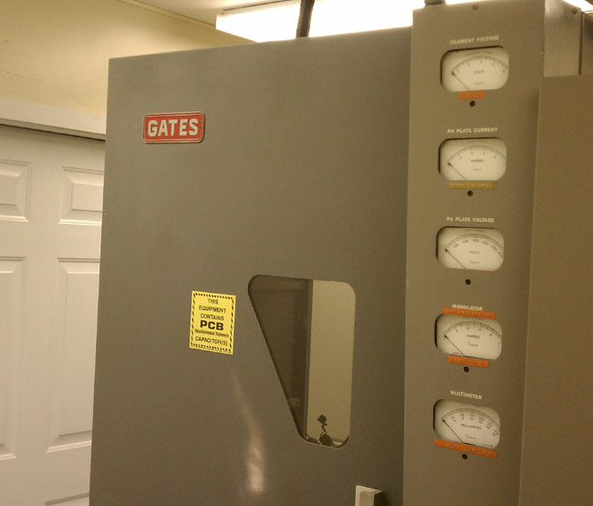
If one considers paradise an FM35A. Going through another iteration of blown transmitter fuses for WEBE, Bridgeport, CT. Yesterday, I spent the afternoon examining the transmitter and found several interesting things:
Fresh arc tracks on the PA cavity and PA loading capacitor
The shoes and bars in the high-voltage contactor were severely pitted
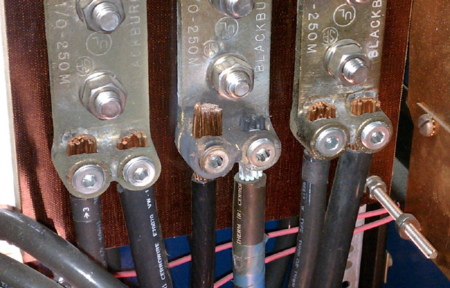
One of the mains phases (middle) in the high voltage supply appears to be heating up, likely due to a loose connection.
Discolored wire on buss bar
I checked and re-tightened all of the mains connections. Apparently, this is an old problem, as the Allen screw was tight. Interestingly, the fuse that was blown was on the red phase, which is different from what it was last time.
I spent the afternoon filing and sanding off the arc track marks in the PA cavity. It is very important to file flat all sharp points that were the result of arcing. Any sharp points will induce corona. I also filed down all of the contacts in a high voltage contactor, which took a fair amount of time. These are soft copper shoes and bars that had so much pitting and carbon I wonder how they didn’t catch on fire. I filed them flat. We were back on the 35A transmitter at full power by 4:30 pm.
If this happens again, I will bring my megger out and check the insulation on the wire between the disconnect switch and the HV power supply.
When I left the site at 5:30, I felt like we did some good work.
This is of interest because of the GE BT-25-A transmitter footage. I do not know the serial number of the WCKY BT-25-A transmitter, but it looks identical to the old WPTR BT-25-A unit which can be seen in this post. As I stated in that missive, I have not heard any transmitter before or since, that sounded as good as this unit. They were really engineering marvels, even in 1999 when this video was shot.
No doubt the MW-50 (no letter) and particularly the DX-50 transmitters are more efficient. In this day and age when many AM stations are just scraping by, overpaying for utilities is not an option. I noticed the Harris MW-50 transmitter with the PDM drawer open. That brings back memories too, those PDM boards were a pain in the rear, as I recall.
There is a propensity among radio engineers to save old equipment. Sometimes I look at something and think, “Man, that cost a lot of money ten or twenty years ago.” Truth be told, much of what is saved will never be used again. This equipment should be scraped or donated to someone who might find it useful. One thing that is most appreciated by Amateur Radio (AKA Ham) operators is old 1 KW tube type AM transmitters. Ham operators love these things and with good reason.
A fair amount of repair work, some cleaning, and a bit of reworking will turn what might have been a useless dust collector into a 160 or 80-meter AM rig and with a good story to boot.
Personally, I’d rather see a Gates BC1T or RCA BTA1R off to a new home than off to the scrap yard. To that end, today we unloaded the BC1T at WLNA to a willing ham. This particular transmitter had last run in 2001 or so and was used as a spare parts supply for other BC1T transmitters owned by the same company. There was no way it would ever work again and truth be told, it really wasn’t needed any longer anyway. Since the Harris MW5B was replaced as the main transmitter by a BE AM6A, the backup transmitter was never used.
Gates BC1T transmitter
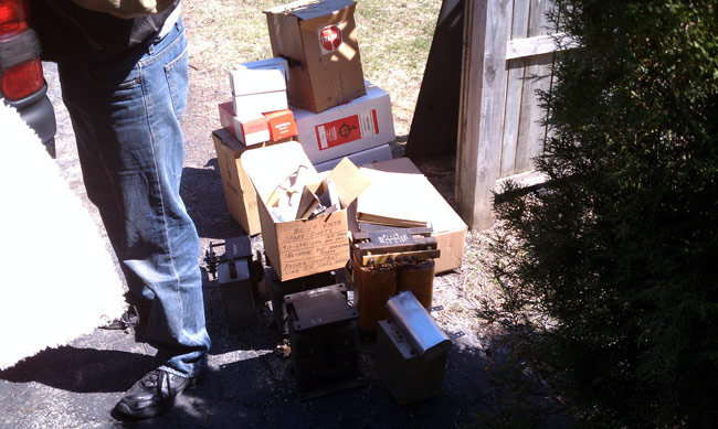
John Aegerter, a frequent commenter on this blog, drove all the way from Madison, Wisconsin to pick it up. Prior to picking up, I removed all of the tubes, transformers, crystals, and glass envelope time delay relays. I packed up the glass objects in a box.
Gates BC1T tubes, transformers and spares
There were several spare tubes and parts which are no longer needed. These went with the rig, along with whatever manuals I could find.
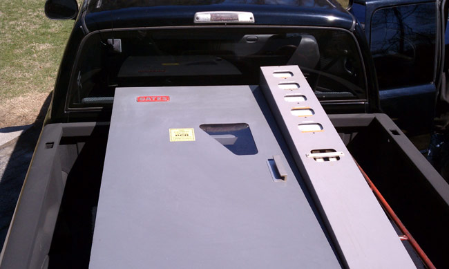
Gates BC1T loaded into pickup truck
The transmitter was then loaded into the back of a Dodge Ram 2500 pickup truck and tarped for its trip back to Wisconsin.
The rumble of thunder this morning let me know that lightning season is upon us here in the Northeast and likely the rest of the country as well. I used to enjoy the odd summer thunderstorm, especially the late afternoon pop-ups that cool off a hot summer’s day. Now whenever I see lightning or hear thunder I wonder if the phone is going to ring. Chances are good that it will not, as I invested many hours of my time and my previous employer’s money into lightning protection at the transmitter sites.
upper atmosphere lightning depiction
I go on the assumption that all tall steel towers will get struck, oftentimes repeatedly, during any particular electrical storm. Back in the day, I took a course by Polyphaser called “The Grounds for Lightning and EMP Protection.” It was a great primer on how to ground and bond equipment at a transmitter site to eliminate current flow, which is the cause of all EMP and lightning-induced failures. When I was in military communications, no expense was spared as they took uptime very seriously. Any downtime was a personal affront to the commanding officer of the unit in question.
Lightning is DC however, it behaves more like 10 KHz – 2 MHz AC. Therefore, lightning and EMP grounding systems need to be designed and installed to accommodate DC through 10 KHz AC voltages. This is easily done by choosing the correct conductors, ground bus bars, and bonding systems.
The other path lighting takes into a transmitter is through the AC mains. Utility company high voltage primary feeds act like large antennas for lightning-induced EMP. Fortunately, much of that is filtered out by the step-down transformers just before the building service entrance. It is still possible, however, for some impulse voltage to make it through the transformers and into the service entrance panel. On older tube type transmitters, this could often damage the plate voltage power supply because of the voltage multiplication factor of the plate transformer. Oftentimes, the transformer secondary would have “holes” punched through the insulation to ground. This is an expensive and time-consuming repair.
I would conservatively estimate that for every $10.00 spent on lightning protection, $1,000.00 dollars worth of damage and downtime is saved. Overall, a pretty good return on investment.
The basics for lightning ground bonding are thus:
Use the lowest inductance wire possible. The industry standard is #2 solid copper, however, if bonded properly, there will be very little current flow inside the transmitter building, so if #2 is not available, then any solid wire up to #8 will work. Tower ground bonding should be as heavy as possible.
Ground all guy anchor points, and bond all guy wires together and to the same ground rod or ground rod system.
Keep the bonding conductors as straight as possible, bends should be long sweeping turns to minimize series inductance.
All metal equipment should be bonded, no rack, telco demark, electrical panel, dummy load, bulkhead entrance grounding bus, combiner, door frame, etc should be left unbonded.
All coax outer shields should be grounded where it comes into the building.
All coax cables should go through a toroid before being connected to the transmitter.
All outdoor bonding connections should be exothermically (CAD welded) bonded to ground rods.
All grounding must go to a common ground point, AKA star grounding point. No individual ground points should be allowed in the building.
Multiple ground rods were installed around the outside perimeter of the building as deeply as possible. Some mountaintop transmitter sites may require special grounding material (Bentonite) and or to have a ground well drilled. Ground conductors should have as much surface area contact with Earth as possible.
The whole idea is to present a low-resistance ground path and keep all of the equipment at the same potential to minimize the current flow between equipment.
For the electrical building service entrance, a series surge protector installed before the service panel is the best method. Several are made and they need to be sized for the building service. A fallback is a parallel surge protector that will provide some protection. On the AC mains connections, any series inductance that can be added to increase resistance to the lightning pulse is good. All AC mains connections to the transmitter should go through a toroid before they are connected to the transmitter. This is a good idea for remote control and mod monitor wiring as well.