Emergency AM replacement antenna

Eventually, disaster will strike. It can range from a fire at the transmitter site to a tornado at the studio.  Someday, every station on the air will be knocked off at the worst possible moment. It is the law of nature.  Perhaps the most difficult disaster to recover from is the loss of a tower at a transmitter site.  An FM tower holds the antenna, therefore, finding a tower or building nearby and placing a temporary antenna there will get the station back on the air in a reasonable fashion.

An AM tower is the antenna, which is much harder to replicate.  One possible solution is to use a temporary wire antenna while the tower is being rebuilt.  This is allowed in FCC 73.1680 emergency antennas, provided the commission is notified of the situation by informal letter.  Directional stations must operate at 25% or less of the station’s licensed power, or demonstrate that radiation limits are not being exceeded in any direction.  That usually can be accomplished by taking a set of monitor points.

A wire antenna can come in several configurations:

  1. The fastest to deploy is the random-length end-fed wire.  This can normally be attached to the existing ATU and tuned up with components on hand.  It requires having an OIB, generator, and receiver to tune, which not every station has.  In addition to that, extra components may be needed in the ATU for tuning purposes.
  2. The next easiest is a tower-length wire ready to deploy.  This is a length of wire equal to the height of the tower, with insulators and supports.  The wire should be supported as high above ground as possible using trees, wooden poles, etc.  Still requires having an OIB, generator, and receiver to tune.  Likely to be within the tuning limits of the ATU components on hand.
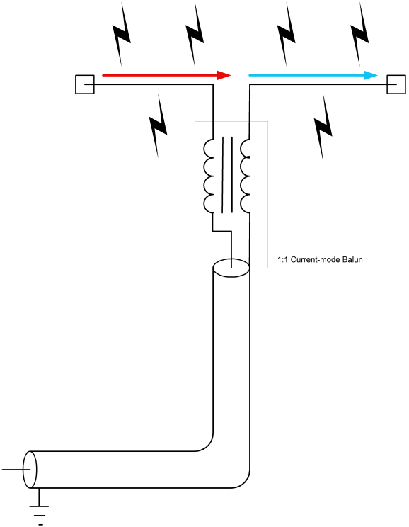
  3. A 1/2 wave dipole tuned for 50 ohms.  This can be connected directly to the transmitter output, thus is the best solution if the ATUs were damaged or otherwise not serviceable.  In this situation, two 1/4 wavelengths of wire are coupled at the center using a 1:1 balun.  Again, this antenna should be supported as high above ground as possible using trees, poles, and other non-conductive supports.  Can be installed in a V, inverted V, or L shape as required.

All three of these choices would likely limit transmitter power output to 1-2 KW.  Choice 3 likely represents the most efficient radiator and can be fabricated ahead of time and stored at the transmitter site.

1/2 wave dipole with 1:1 balun

To make a 1/2 wave dipole, cut two lengths of wire using the formula L(feet)=246/F(MHz).  This formula does not account for a velocity factor of 90%, which is typical for stranded wire.  The reason is, since an MF dipole antenna is necessarily going to be lower than 1/2 wavelength, it is better to start the antenna a little long and trim it to size for a 50-ohm impedance.  If commercially made insulators are not available, insulators can be made from non-conductive materials like PVC conduit, PEX, plexiglass, etc.  The insulators on the ends of the wire need to account for the voltage peak that will occur there.  If small “dogbone” type porcelain insulators are used, string three or four of them together using nylon or poly rope.  The insulator needs to be able to withstand 8-10 KW of power under full modulation.

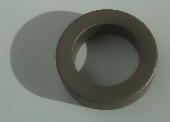
A 1:1 balun will distribute the RF currents evenly on both wires, which will help improve efficiency and coverage.  Most Ham Radio Baluns are not designed to work below 1.8 MHz and therefore, will not work for this purpose.  A balun can be made with a ferrite toroid made from 68, 73, 77, or type F material.  A good choice would be Amidon FT-290-77 or FT-290-F.  The type F material has a higher AL value, thus fewer turns are needed.  In addition to that, high voltage insulated wire should be used to wind the balun.

1/2 wave dipole antenna current voltage distribution

Since, in a 1/2 wave dipole configuration, the voltage is at a minimum at the center of the antenna, and current is at a maximum, some attention needs to be paid to wire size as well.

Amidon ferrite torroid core

To give a good idea of wire sizes required, some basic information is needed.  For a 1 KW station, it is assumed that the carrier will be modulated to 100 percent, therefore the peak envelope power will be 4 KW.  If the station is asymmetrically modulated, add another kilowatt.  Therefore, the maximum current formula is I=√(P/R).  P is the power in watts, or 5,000 and R is the radiation resistance or 50 ohms, thus I=√(5000/50) or 10 amps.   The maximum voltage is E=√(P x R) or E=√ (5000 x 50) or 500 volts.  For a safety factor, multiplying these values by 1.5 is recommended.  That will likely account for any impedance differences due to ground proximity and so forth.  Therefore for a 1 KW station, the dipole antenna should be designed for 15 amps and 750 volts.

For a 2 KW station the peak envelope power for an asymmetrically modulated transmitter is 10 KW, thus it follows that 30 amps and 1500 volts are safe working figures.

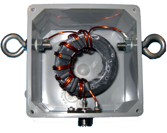
With the proper torroid core, a turns count of 7-10 turns bifilar will suffice.  Since it is a 1:1 balun, the turns count on both sides of the transformer will be the same.  The balun then should be placed in a suitable water proof housing designed to be attached to the center of the dipole antenna.  This is a good example of a commercially available 5 KW 1:1 balun for amateur radio use:

1:1 balun designed for center of 1/2 wave dipole antenna

The antenna can be fed with RG-8, RG-8X, RG-8A, RG-214 or any other coax this is capable of handling the peak envelope power of the radio station.  The connector can be UHF, N, LC, etc.  In some cases, the may be easier to simply omit the connector and connect the coax to the balun using some type of strain relief on the cable coming out of the box.

Once this antenna is made, a bit of tuning may be required to bring it to 50 ohms.  This can be done with a bridge and generator, or with the transmitter on low power.  Either way, the measurements must be taken with the antenna at operating height as the distance to ground will effect the termination point impedance.  It may require some trial and error.

In all, a good backup antenna can be made for about $50-60 or so.  A little bit more if fancy transmission line is used.  Well worth the expense and effort to have something ready to go in a moment’s notice.

Update: I’ve been fooling around with this on EZNEC, it may not be that easy to do, especially with the lower frequencies in the AM band.  The antenna needs to be at least 0.06 wave length above ground to perform correctly.  Somewhat lower over better ground conductivity, e.g. ground radials.  Even at this height, it needs to be lengthened significantly to get the feed point impedance close to 50 ohms.

Sound Cards for Broadcast Use

Computer audio sound cards are the norm at nearly all radio stations. I often wonder, am I using the best audio quality sound card?  There are some trade-offs on the quality vs. cost curve.  At the expensive end of the curve, one can spend a lot of money on an excellent sound card.  The question is, is it worth it?  The laws of diminishing returns state: No.  High-quality reproduction audio can be obtained for a reasonable price.  The one possible exception to that rule would be production studios, especially where music mix-downs occur.

I would establish the basic requirement for a professional sound card is balanced audio in and out, either analog, digital, or preferably, both.  Almost all sound cards work on PCI bus architecture, some are available with PCMCIA (laptop) or USB.  For permanent installations, an internal PCI bus card is preferred.

Keeping an apples: apples comparison, this comparison it limited to PCI bus, stereo input/output, and analog and digital balanced audio units for general use.  Manufacturers of these cards often have other units with a higher number of input/output combinations if that is desired.   There are several cards to choose from:

The first and preferred general all-around sound card that I use is the Digigram VX222HR series.   This is a mid-price range PCI card, running about $525.00 per copy.

Digigram VX222HR professional sound card

These are the cards preferred by BE Audiovault, ENCO, and others. I have found them to be easy to install with copious documentation and driver downloads available online.  The VX series cards are available in 2, 4, 8, or 12 input/output configurations.  The HR suffix stands for “High Resolution,” which indicates a 192 KHz sample rate.  This card is capable of generating baseband composite audio, including RDS and subcarriers, with a program like Breakaway Broadcast.

Quick Specs:

  • 2/2 balanced analog and digital AES/EBU I/Os
  • A comprehensive set of drivers: driver for the Digigram SDK, as well as low-latency WDM DirectSound, ASIO, and Wave drivers
  • 32-bit/66 MHz PCI Master mode, PCI and PCI-X compatible interface
  • 24-bit/192 kHz converters
  • LTC input and inter-board Sync
  • Windows 2003 server, 2008 server, Seven, Eight, Vista, XP (32 and 64 bit), ALSA (Linux)
  • Hardware SRC on AES input and separate AES sync input (available on special request)

Next is the Lynx L22-PCI.  This card comes with a rudimentary 16-channel mixer program.  I have found them to be durable and slightly more flexible than the Digigram cards.  They run about $670.00 each.  Again, capable of a 192 KHz sample rate on the analog input/outputs.  Like Digigram, Lynx has several other sound cards with multiple inputs/outputs which are appropriate for broadcast applications.

Lynx L22-PCI professional sound card

Specifications:

  • 200kHz sample rate / 100kHz analog bandwidth (Supported with all drivers)
  • Two 24-bit balanced analog inputs and outputs
  • +4dBu or -10dBV line levels selectable per channel pair
  • 24-bit AES3 or S/PDIF I/O with full status and subcode support
  • Sample rate conversion on digital input
  • Non-audio digital I/O support for Dolby Digital® and HDCD
  • 32-channel / 32-bit digital mixer with 16 sub outputs
  • Multiple dither algorithms per channel
  • Word, 256 Word, 13.5MHz or 27MHz clock sync
  • The extremely low-jitter tunable sample clock generator
  • Dedicated clock frequency diagnostic hardware
  • Multiple-board audio data routing and sync
  • Two LStream™ ports support 8 additional I/O channels each
  • Compatible with LStream modules for ADAT and AES/EBU standards
  • Zero-wait state, 16-channel, scatter-gather DMA engine
  • Windows 2000/XP/XPx64/Seven/Eight/Vista/Vistax64: MME, ASIO 2.0, WDM, DirectSound, Direct Kernel Streaming and GSIF
  • Macintosh OSX: CoreAudio (10.4)
  • Linux, FreeBSD: OSS
  • RoHS Compliant
  • Optional LStream Expansion Module LS-ADAT: provides sixteen-channel 24-bit ADAT optical I/O (Internal)
  • Optional LStream Expansion Module LS-AES: provides eight-channel 24-bit/96kHz AES/EBU or S/PDIF digital I/O (Internal)

Audio Science makes several different sound cards, which are used in BSI and others in automation systems.  These cards run about $675 each.

Audio Science ASI 5020 professional sound card

Specifications:

  • 6 stereo streams of playback into 2 stereo outputs
  • 4 stereo streams of record from 2 stereo inputs
  • PCM format with sample rates to 192kHz
  • Balanced stereo analog I/O with levels to +24dBu
  • 24bit ADC and DAC with 110dB DNR and 0.0015% THD+N
  • SoundGuard™ transient voltage suppression on all I/O
  • Short length PCI format (6.6 inches/168mm)
  • Up to 4 cards in one system
  • Windows 2000, XP and Linux software drivers available.

There are several other cards and card manufactures which do not use balanced audio.  These cards can be used with caution, but it is not recommended in high RF environments like transmitter sites or studios located at transmitter sites.  Appropriate measures for converting audio from balanced to unbalanced must be observed.

Further, there are many ethersound systems coming into the product pipeline which convert audio directly to TCP/IP for routing over an ethernet 802.x based network.  These systems are coming down in price and are being looked at more favorably by broadcast groups.  This is the future of broadcast audio.

OET65? What is that?

Readers of this blog will know that I enjoy history.  Old photos are great things to study, as they say, pictures… thousand words… etc.  Here is one that I found on the RadioMarine website:

WER radio, 192X?
WER radio, 192X?

Here we have three gentlemen at work at an early radio station.  It seems like a posed shot, nobody can study a meter that intently.  They are sitting directly in front of the transmitter and it looks like the antenna tuning coils are behind the operating position.  Notice the open wire and transmission line, presumably all under power when this picture was taken.  There seems to be no concern about RF or electrical safety, I suppose it was trial and error back then, with a heavy price paid for error.  Meter boy should be careful not to back up too far, if he does, he’ll get a little behind in his work.

We’ve been a little busy this last week, I’ll catch up on the blogging this weekend, there are many things to tell.