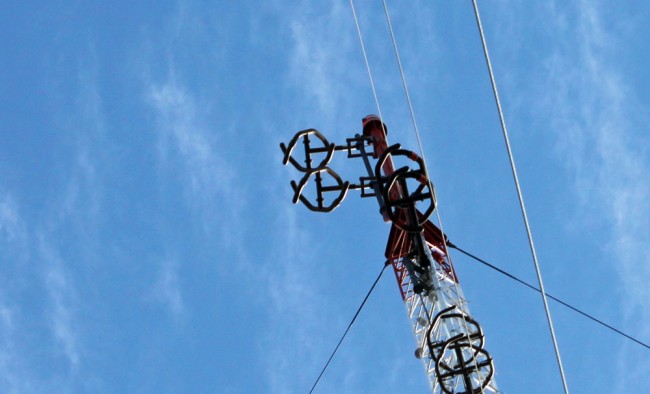
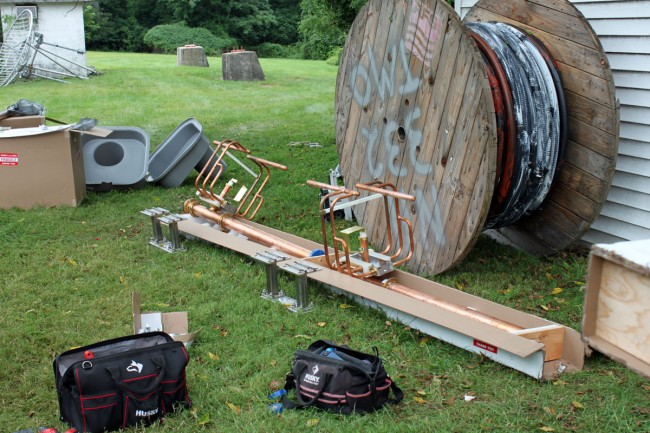
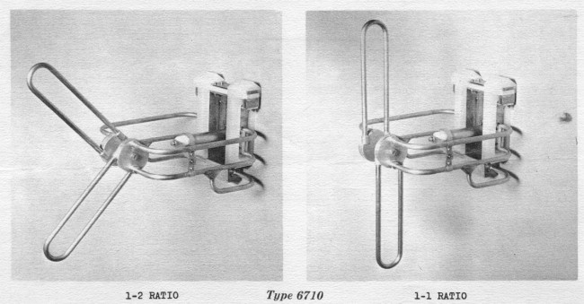
Several companies make variations of this antenna; Scale FM-CL is a lower-power version that is used mostly by translators. They are highly directional and can be installed in a vertical, horizontal, or cross-polarized (45-degree slant) manner. This model input power is 5 KW per bay and the manufacturer’s specification is for 1.28:1 or less VSWR across the entire FM band. In the slant configuration, which Shively states is right-hand circularly polarized, the gain is 4.03 dB.
I recently did some work onsite for WXMD, California, Maryland. They were having some issues with high reflected power readings on their transmitter and suspected an antenna or transmission line problem. The station has been on the air for about 10 years and began having issues late last year after a thunderstorm passed through the area.
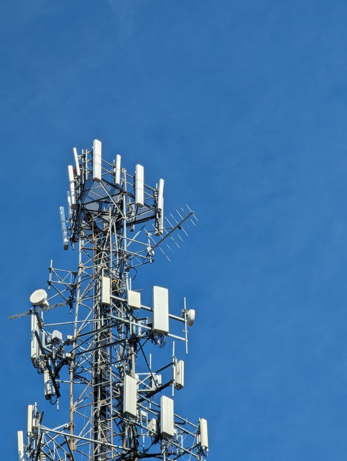
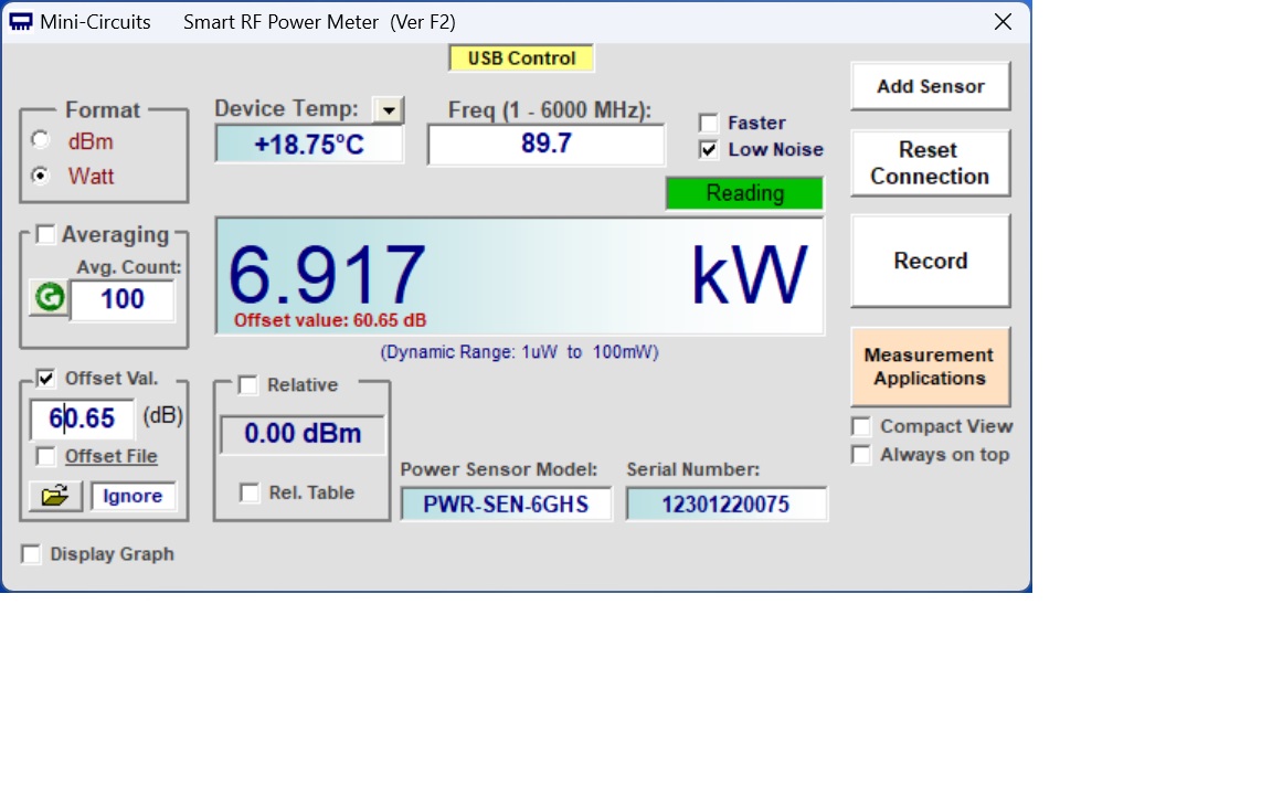
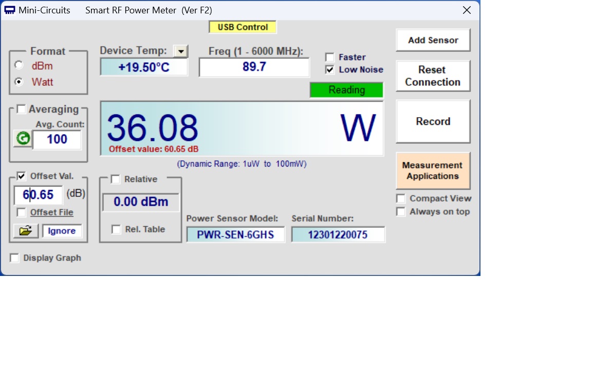
The main issue was that the transmitter was showing 243 watts of reflected power with 9800 watts of forward power, while the inline watt meter showed 37 watts. As part of the repairs, a new 1 5/8 transmission line was run up the tower replacing the old line which was damaged at the power divider input connector. A new power divider was also installed. Was the antenna still defective? Was the new transmission line and/or power divider defective? Was there an issue with the inline watt meter? Questions, questions, questions…
Thus, several sweeps were needed to verify things:
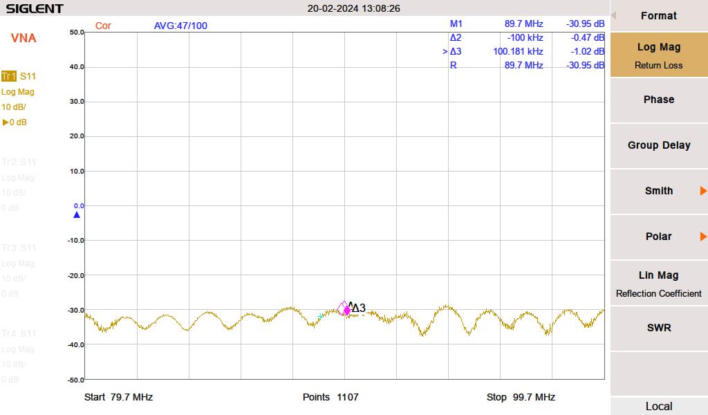
This antenna has a power divider that splits the power between a southeast-facing antenna bay and a southwest-facing antenna bay. To be sure that we were not dealing with a bad connector or transmission line, the line was swept in isolation from the input of the inline watt meter to the input of the power divider. This showed that the transmission line, connectors, elbows, and inline watt meter were all good.
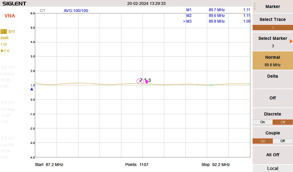
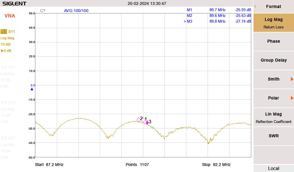
Next, each antenna bay was swept individually. The power divider port going to the disconnected antenna was terminated with a known good 50-ohm load.
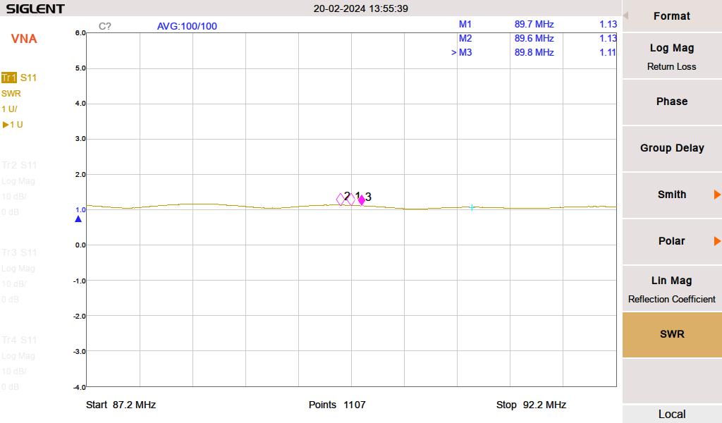
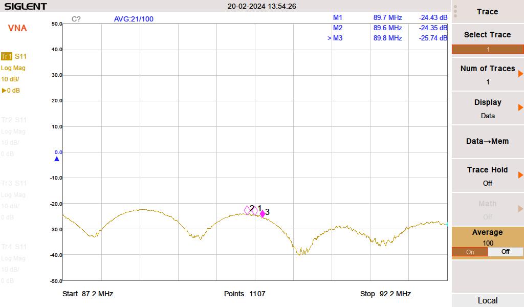
Once the individual bays, jumpers, and power divider tested good, the entire antenna system was swept.
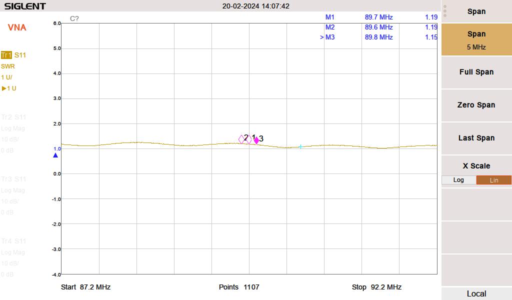
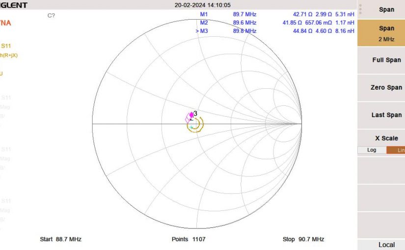
With everything connected, the SWR showed 1.19:1. Not ideal but not terrible either. The inline watt meter readings were verified with a precision watt meter and the final SWR calculated by hand was 1.16:1.
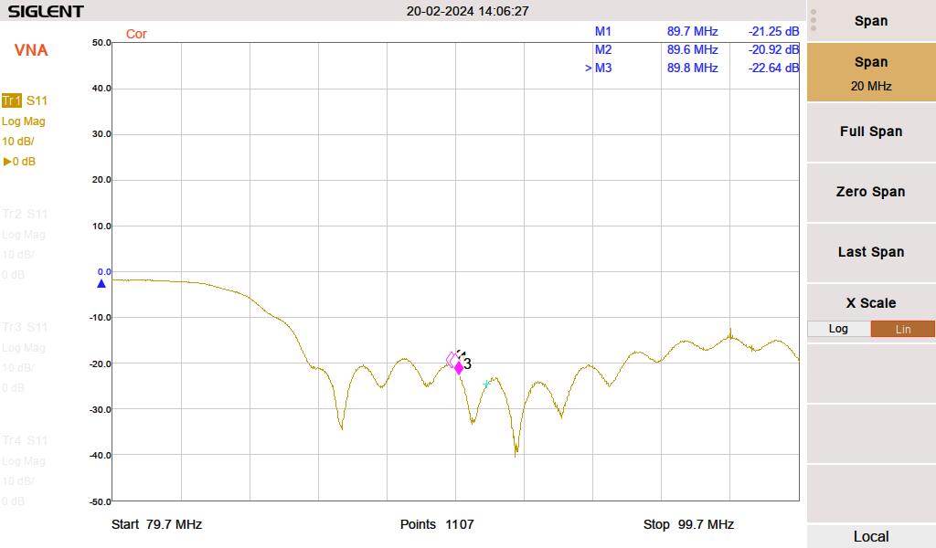
Therefore, the antenna system is performing within the manufacturer’s specifications.
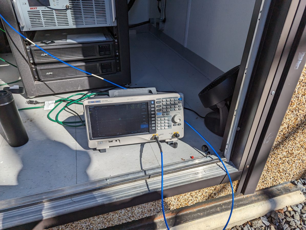
The American Amplifier Technology inline FM watt meter was then checked with a precision power meter. The readings on that device were more or less in line with the precision power meter, thus the transmitter directional coupler is out of calibration.
The transmitter shelter is just large enough for one rack. Thankfully, the weather was cooperative, we were able to work outside. Overall, it was a productive trip and an enjoyable experience.



Nice detective work here, Paul.
Does the TX manufacturer consider this calibration a maintenance item, and if so, how often do they suggest users perform a calibration?
Normally, FM transmitters do not need to have the power meters recalibrated once they leave the factory. I think this one had a circuit board replaced.
Could some of the VSWR just be from being at the low end of the band into a broadband antenna?
Mike, that is exactly what is going on with the VSWR. Looking at the rest of the FM band, the return loss/VSWR is better.