Anytime a new transmitter is installed or major changes to an FM transmission system are implemented, the performance measurements described in FCC 73.317 should be completed to ensure no interference to other radio services. This is becoming a larger issue with the advent of LTE and 5G mobile data. These services along with E911 and other mobile services are often co-located at FM transmitter sites.
The FCC stipulates that emissions removed from the carrier by more than 600 KHz must be attenuated 80 dB below the carrier. These days, that is not enough. We have had issues with older tube-type transmitters interfering with cellular and mobile data service, even though they met or were far below the FCC specification. The first in, first out rule also didn’t seem to matter either. Those mobile phone providers paid a lot of money when they purchased chunks of RF spectrum at auction, and the FCC will side with them if there is any dispute.
Having a record of measurements that show compliance with the FCC regulations can go a long way in heading off any future problems. I make measurements out to the 10th harmonic.
To get the best results, I have been using a couple of high-pass filters from Mini-circuits.
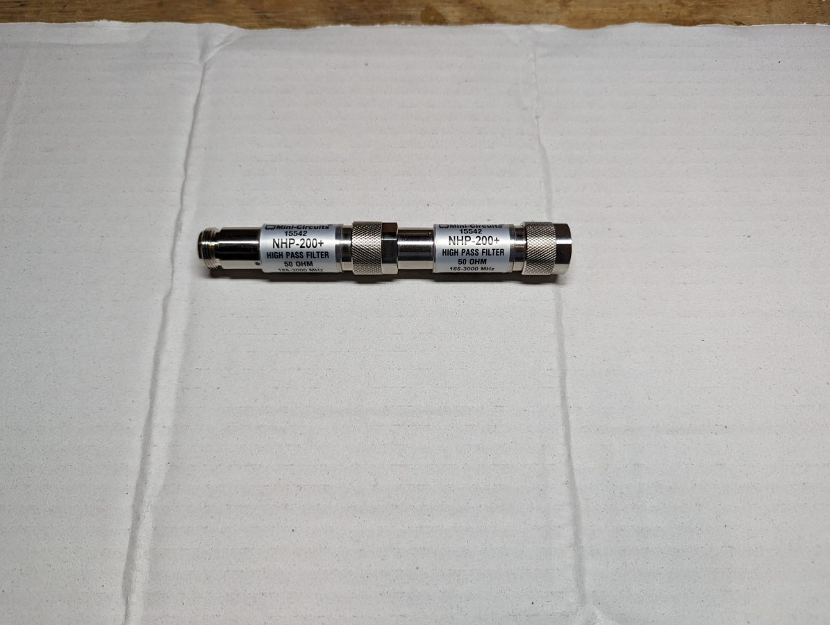
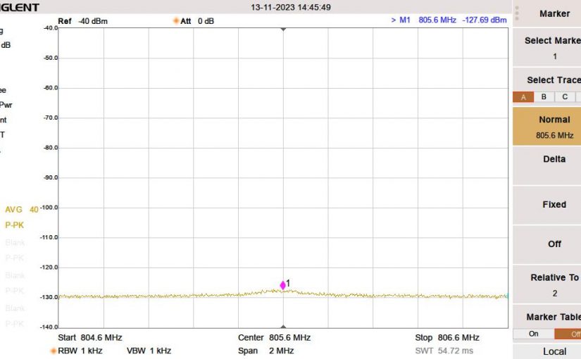
These attenuate the carrier power seen by the spectrum analyzer by approximately 90 dB depending on the frequency. That allows the instrument noise floor to be lowered to -130 dB which should be well below any receiver noise floor being used by other wireless services.
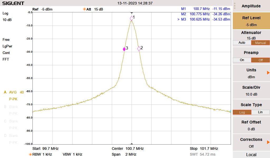
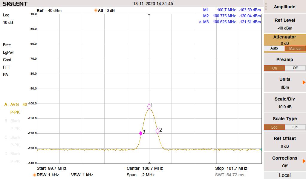
The carrier is attenuated by 92.44 dB. The rest of the measurements are made with the attenuation set to zero and the preamp turned on. For the lowest FM frequency, 88.1 MHz, the filters are on the edge of their shoulder at the 2nd harmonic. I measured the return loss and found that they matched the manufacturer’s datasheet.
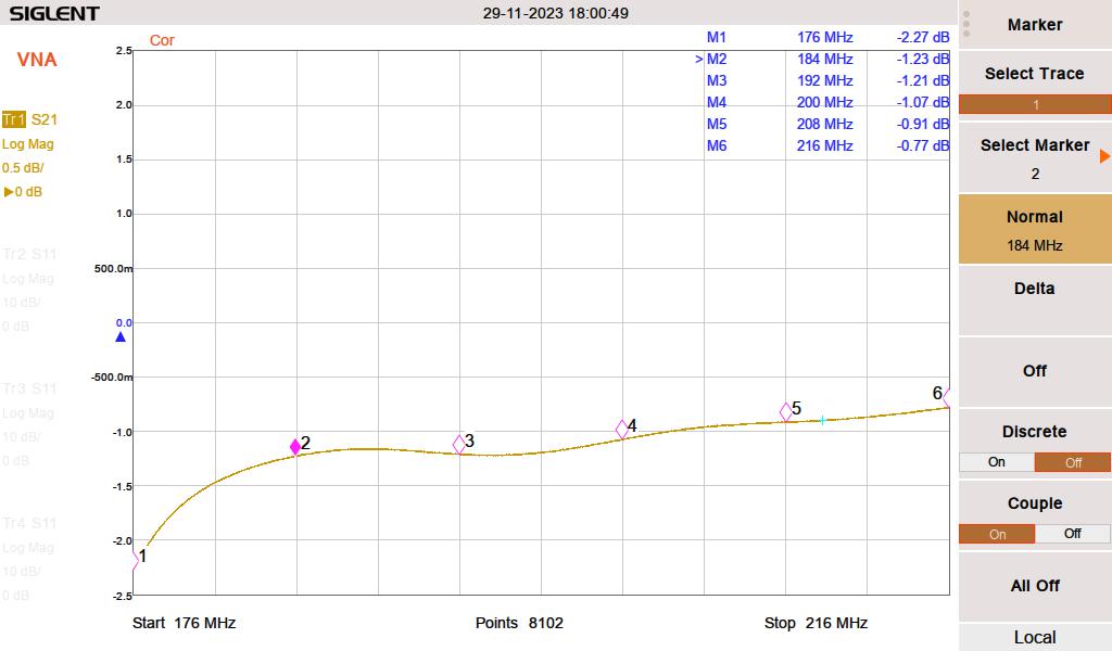
That loss is counted as attenuation for the second harmonic. For the rest of the harmonics, I used 0.5 dB attenuation, which represents connector loss. I could have also measured the cable loss at each harmonic, but that seems unnecessary, given several of the readings were below the noise floor.
To speed things along, I made this handy Excel spreadsheet, which does all of the calculations for me:
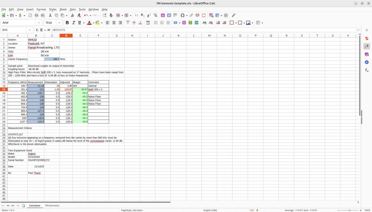
A copy of that spreadsheet can be downloaded: FM Harmonic template
Once completed, I printed a copy and put it with the station maintenance log at the transmitter site.



HI
GOOD AFTERNOON
MY NAME IS ANAEL MELLO,
I’M AN ELECTRONIC ENGINEER,
I WOULD LIKE TO PURCHASE THE HIGH PASS FILTER ( NHP – 200 + HIGH PASS FILTER 50 OHM, 185 – 3000 Mhz.
HOW DO I BUY, IS THERE A REPRESENTATIVE IN BRAZIL?
MY ZAP IN BRASIL: 55 31 985822000
THANKS,,
Hello Anael,
Contact Mini Circuits directly: https://www.minicircuits.com/