Sometimes it is obvious and relatively easy, other times not so much. This summer we have had wave after wave of afternoon thunderstorms. It is almost like living in Florida; almost, but not quite. Anyway, with the storms occasionally comes some lightning damage. At most of the transmitter sites we service, every step has been taken to ensure good grounding and adequate surge suppression. This is especially true of sites that have been under our care for a few years. Even so, occasionally, something gets through. After all, those five-hundred-foot steel towers do attract lightning.

This is the output section of the BE AM5E transmitter at WROW. The transmitter got pretty trashed; a bad PA module and power supply and this capacitor in the output section. This particular transmitter is 14 years old and this is the first major repair work we’ve had to do it.
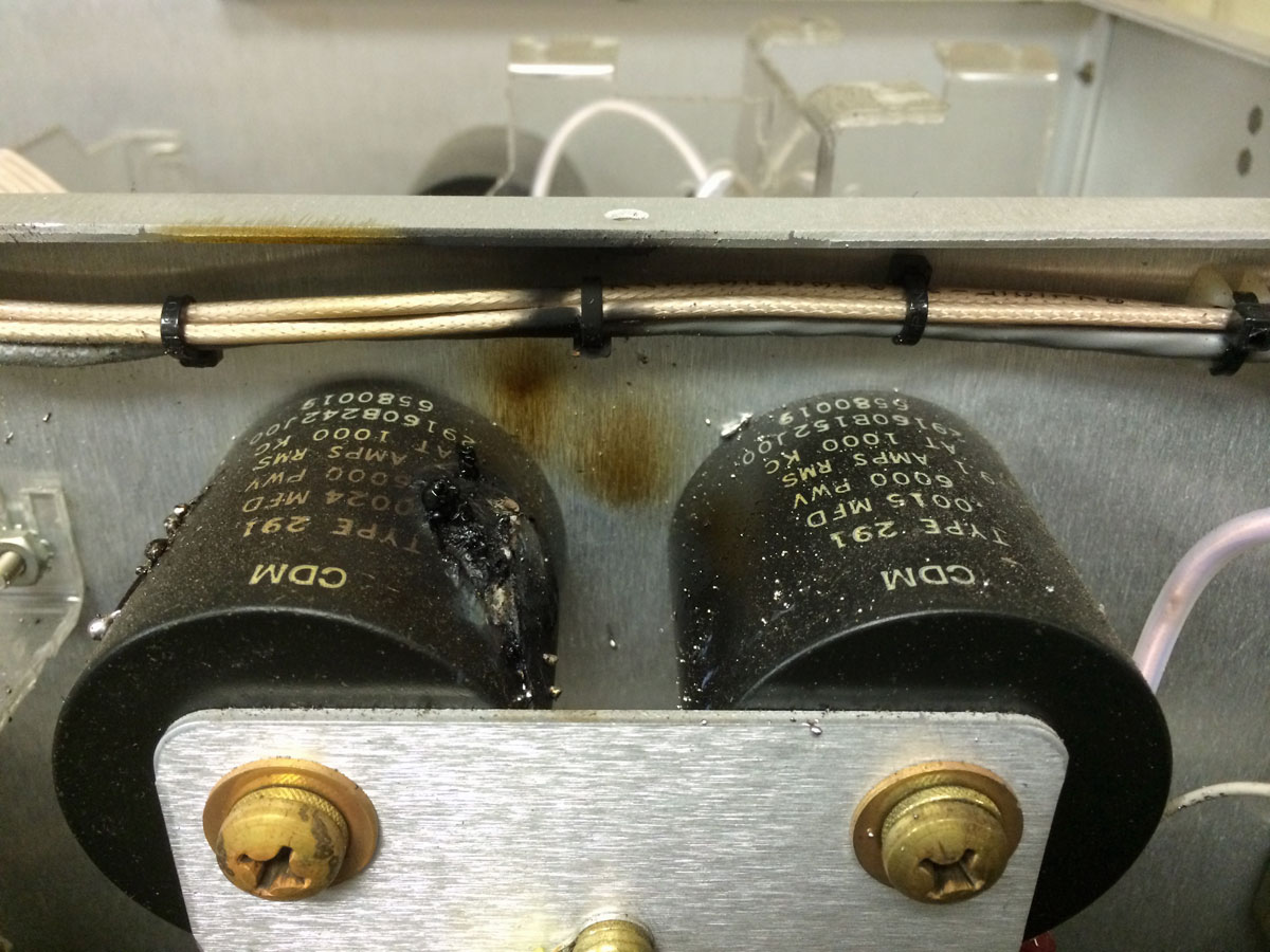
The capacitor was fairly easy to change out. As a general precaution, both capacitors were changed. There was a spare PA module and power supply on the shelf, thus the transmitter was returned to full power relatively quickly.
The rest of the antenna system and phasor were inspected for damage, a set of common point impedance measurements taken, which showed that no other damage was sustained.
Next, the 30 year old Harris SX2.5 A transmitter at WSBS. This failure was slightly more exotic; the transmitter started randomly turning itself off. The culprit, in that case, was this:
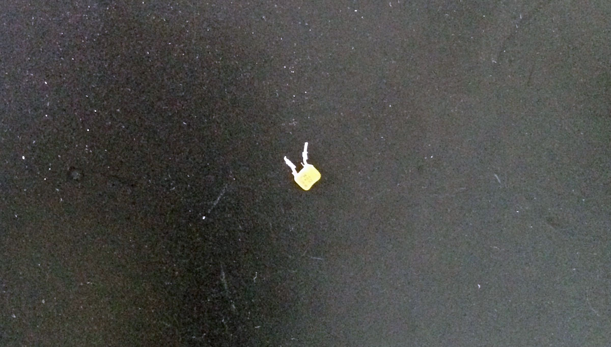
Literally, a two cent part. The transmitter remote control uses optoisolators. The inputs to these opto-isolators are RF bypassed to ground on the back of the “customer interface board.” After determining that the remote control was not malfunctioning, it was down to either a bad opto-isolator or something really silly like a bypass capacitor. This capacitor was on the ground side of the remote off terminal. It shows short on the capacitance meter and 4.1 K on the ohm meter, just enough to randomly turn the opto-isolator on and shut down the transmitter. Being a Harris transmitter, removing and replacing the “customer interface board” was no easy matter. Overall, it took about three hours to find and repair this problem.

At least your transmitter was turning off. Many years ago, the SX-1 I care for had a bypass cap go flaky, too. It was on the high power remote-on circuit. Transmitter was coming on by itself. Being a daytimer on a clear channel, this was NOT a good thing.
On a BE AM500E, I had similar problems, first on one power level, then another, so I shotgunned out all the optos to fix that issue.
Harris used these bypass caps in transmitters and their Medalist consoles. I had one short out on the oscillator board in an SX-1A. In the Medalist it took time to cut PC board clads to narrow down the culprit as they had one on each leg at each chip. I had to do that several times. Not fun.
I just repaired a Nautel ND-10 with micas that looked just like the first picture…. Five micas total… they spewed their guts out and made quite a mess….not an easy repair in the combiner and rf filter . This should have been a three cabinet transmitter instead of packing everything into two cabinets.
Moderator…. make that the #2 picture