The open delta three phase service

Several months ago, I drove up to an FM transmitter site, looked up at the utility pole, and saw this:

Three Phase open delta transformer bank

Three-phase open delta is a bad hombre.  Most, if not all, transmitter manufacturers will void the warranty of any transmitter connected to a service like this.  What is perplexing is it appears that all three phases are available on the primary side, why would this be necessary? Perhaps it was not always so at this location.  Regardless, this was the source of power for 20 KW FM transmitters since 1958 until we moved it to a new building last month.

According to a GE publication on transformers, open delta 3 phase power is undesirable because:

Although this connection delivers three-phase currents which are approximately symmetrical to a three-phase symetrical load, the currents flowing in the high voltage circuit are not equal nor are they 120 degrees apart.  The maximum safe output of the bank operating in this manner is 58% of a 3 pot Wye/Delta bank. The system is grossly unbalanced, both electrostatically and electromagnetically.

Schematically, it looks like this:
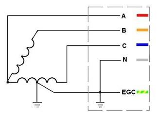
3 Phase open delta power

Regular 3 phase delta looks like this:
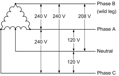
3 phase delta power
3 phase delta power

Most utility companies will not hook up 3 phase delta on the customer side anymore because the “high” or “wild” leg, which as shown in the diagram runs a good deal higher than 120 volts to neutral.  Hook up a high leg to a single phase 120 volt piece of equipment and wait for the power supply to blow up.  Also true with 277-volt lighting circuits, as my assistant once found out with the Coke Machine in the break room.  The new 3 phase service will almost invariably be 208 wye unless there is some very compelling reason, which is fine.

There are many ways to get around three phase open delta, perhaps the best is a rotary phase converter.  This piece of equipment will take a 240-volt split phase and add a third leg.  These legs will not be 120 degrees apart, as they would be in a true three-phase, however, they will be close enough that 3 phase motors and transformers will be happy.
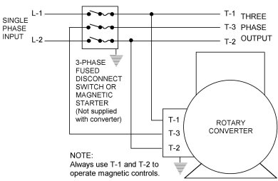
Rotary Phase converter

This leads to an unbalanced voltage/current condition which needs to be accounted for in the design of the unit.  The second way to do this is to power a three-phase generator with a split-phase motor.  This will completely isolate the 3 phase equipment from the utility service and provide for true three phase power.

The downside to any motor/generator or rotary converter is moving parts and conversion inefficiencies.  At any transmitter site that uses this type of equipment, either a backup power converter or a lower power split phase backup transmitter should be installed.  With all mechanical things, eventually, this will need to be repaired and it would suck to be off the air while that is happening.

Regardless of any of that, this particular service is about to be disconnected permanently.  Good riddance.

The hard restart

Sometimes there is just no way around it, especially with some modern equipment:

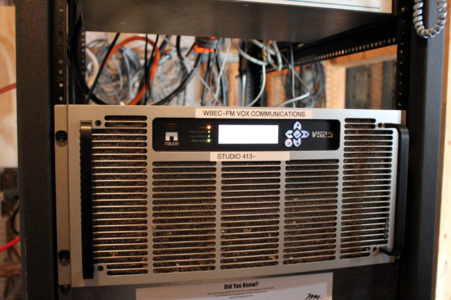
Hard restart, Nautel VS2500 transmitter

This Nautel VS2500 transmitter got all cranky after lightning struck the tower (or nearby) on Friday night.  Thunderstorms in February are not unheard of, but they are unusual, at least in the Northeastern United States.

Nautel VS2500 FM transmitter, WBEC-FM, Pittsfield, MA

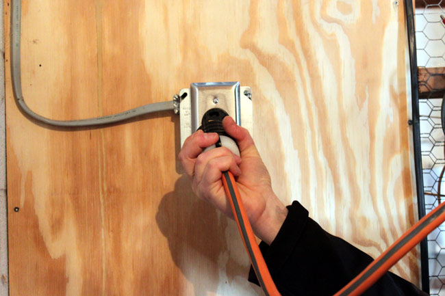
Anyway, the transmitter would not reset or restart via remote control, therefore, we had to ride the chair lift to the top of the hill and pull the plug to reset its logic and start over again.

Bousquet Ski Area Chair lift

At least the trip up to the transmitter site was scenic.  We had to wait a day for the winds to calm down, but all in all, not a terrible day.  Did I mention the scenery?

Side benefits

Some people work in offices and make lots of money. Others work outside, oblivious to the world going on around them. A fortunate few, myself included, get to work in many different environments, and appreciate them all.

A week or so ago, at the end of the day, I was carrying my tool bag back to the truck and was surprised to see this view:

View looking west from the WRKI transmitter site, Brookfield, CT

The picture really does not do justice. A much wider view is required to get the full effect.  It looked like the sky was on fire, something out of a science fiction movie.

Then again, yesterday, I spent the day in a dank, smelly basement tracing out telephone wires.  In the end, it all evens out.

The Generator and the UPS

An issue I had to deal with recently; was an unstable generator/UPS relationship.  When the generator was running under load, it surged repeatedly causing the UPS to drop out and not recharge.  Eventually, the UPS ran out of juice and shut down, killing the power to the Sine Systems remote control and telephone system.  Of the two, the remote control was the biggest pain to fix, as it lost its timed commands and would not reduce power at sunset for the associated class D AM station.

What went wrong?  This is a chart of typical problems with generators operating UPS loads:

SymptomPotential Problem
Fail to “lock on” to generator powerImproper generator frequency or voltage
Poor generator regulation
Unrealistic performance requirements
Instability of generatorVoltage regulator sensitivity
Control loop compatibility
Filter/control interaction
Governor or AVR problem
Fail to sync bypassMetering errors
Instability at specific load levelsControl loop compatibility
Instability at load changesControl loop compatibility
Metring errorsGenerator output voltage distortion
Loss of voltage controlExcess capacitance in filters vs. load

Table courtesy of Cummins Power Generation.

Generator excitation methods can be the culprit in many of these situations.  Generators often use one of three types of excitation for their field coils:

  • Shunt-excited SCR (silicon-controlled rectifier)
  • Shunt-excited PWM (pulse width modulation)
  • PGM (permanent magnet generator)

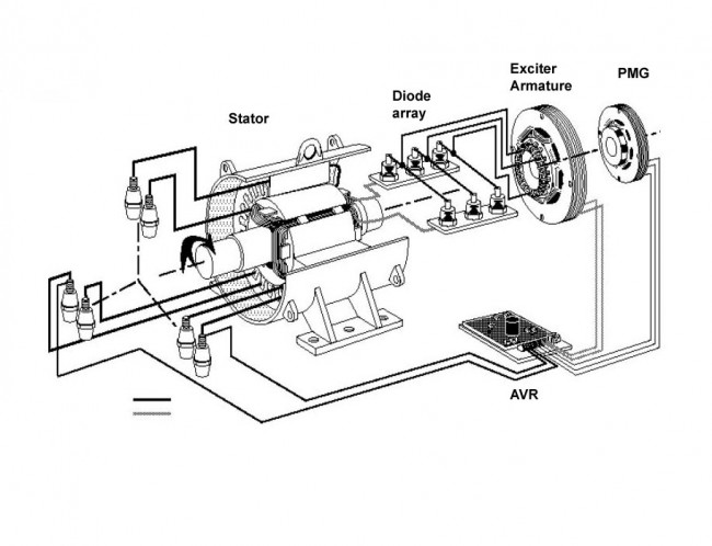
Of the three, the permanent magnet generator is the most stable since the AVR (automatic voltage regulator) is powered by a separate small generator which is unaffected by the load on the main generator output.  SCR and PWM both use the generator output windings, which makes them susceptible to load-inducted voltage distortion brought on by non-linear loads.  Therefore, in locations where large UPSs are known to be part of the load, PGM-excited generators are the best choice.

PMG generator diagram

Sometimes, the generator is already in use before the UPS is installed.  In that case, there are some remedial steps that can be taken.  The speed which the voltage regulator reacts to changes in the load is often the culprit in many of these situations.  It may seem counterintuitive, however, the faster the AVR reacts, the more fluctuations there will be in the voltage and frequency.  A UPS can operate under a wide range of voltages and frequency, provided they do not rapidly change.

Depending on other loads, it may be necessary to dampen the gain on the AVR to slow it’s reactions down.  This will work if there are no large intermittent starting loads on the generator such as air conditioning compressors.

Another method would be to delay the UPS transfer to generator power until after all the other loads have been satisfied.  This will ensure that the generator voltage and current fluctuations are damped by the existing load.

The generator’s size needs to account for the equipment attached to the UPS and the battery charging load. With a larger UPS, the battery charging load can be significant. Generators that are improperly sized will not be made to work under any circumstances, hence the “unrealistic performance requirements” noted in the chart above.

You can read the entire Cummins Power white paper on generators powering UPS loads here.