The Ground Loop

Audio Engineers will know this subject well.  Grounding has many purposes, including electrical safety, lightning protection, RF shielding, and audio noise mitigation.  Although all types of grounds are related in that they are designed to conduct stray electrons to a safe place to be dissipated, the designs of each type are somewhat different.  What might be an excellent audio ground may not be the best lightning ground and vice versa.  Sometimes good audio grounds can lead to stray RF pickup.

The basic ground loop looks something like this:

Ground Loop schematic

Where RG should equal zero, in this representation it is some other resistance.  This causes a different potential on the circuit (V1), which in turn causes current to flow (I1).  It is that unexpected flow of current that creates the problems, causing voltage (V2) to be induced on another part of the circuit.  In cabling applications, this will result in a loud, usually 60-cycle hum impressed on the audio or video being transmitted through the cable.

The resistance can come from something as mundane as the length of the conductor going to ground. This can often happen when using shielded audio wire in installations when the connected equipment is already grounded through the electrical plug.

There are two proven methods for eliminating ground loops, both of which are best implemented in the design phase of construction (aren’t most things).
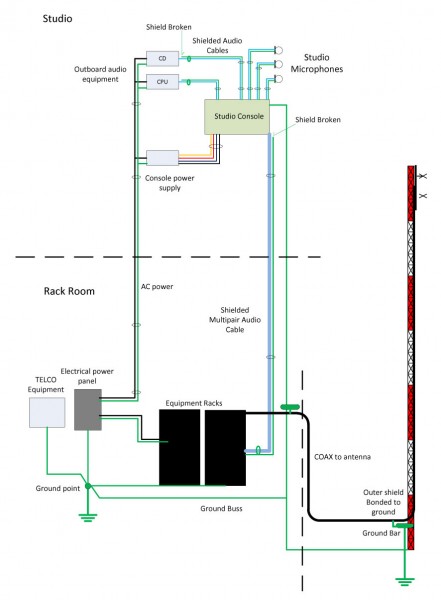
Radio Station Common Point Grounding

The first is a single ground point topology, also known as a common point or star grounding system.  A common ground system consists of one grounding point or buss bonded together so that it has the same potential.  All grounded equipment is then connected to that point creating a single path to ground.  All modern electrical equipment has a path to ground via the third prong of its electrical cord.  Problems can or will occur when audio equipment is plugged into separate AC circuits, grounded via the electrical plug, and then tied together via an audio ground.  The longer the separate grounding paths, the more severe 60 cycle (or some harmonic thereof) hum can result.

To eliminate this problem, the shields should be broken at one end of the audio cable.  Never cut the third prong off of an electric cord, which can create another problem called electrocution.  Given the choice between a ground loop and electrocution, I’d stay away from electrocution, mine or somebody else’s.

For installations in high RF fields, the open shield or ground drain can act like an antenna.  In those situations, the open end can be bypassed to ground using a 0.01 uf ceramic disk capacitor. Electrically, this will look like an open at DC or 60 cycles, but allow stray RF a path to ground.   This problem can be a common occurrence when studios are co-located with transmitters.
Differential Signaling

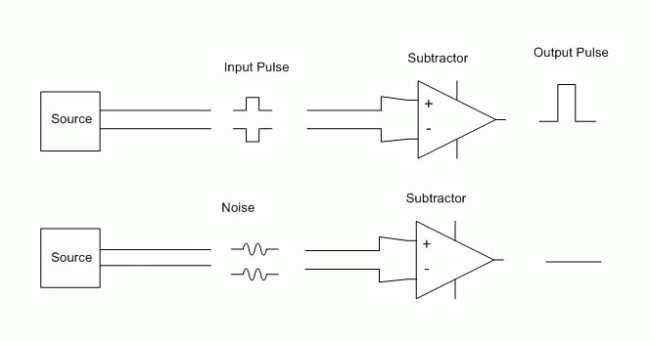
The second is by using balanced audio or differential signals as much as possible.  This poses a problem for those stations that use consumer grade components, especially in high RF fields.  For shorter cable lengths, two or three feet, it is usually not a problem.  Anything beyond that, however, and trouble awaits.

It is relatively easy and inexpensive to convert audio from unbalanced to balanced.  As much as possible, equipment and sound cards that have balanced audio inputs and outputs should be used. In the end, it will simply sound better to use higher quality equipment.  Also, longer cable runs need to be properly terminated at both ends.

Installing equipment using good engineering principles and techniques will eliminate these problems before they start.

FM Stereo vs station coverage

There are a few FM stations around here that intentionally broadcast in mono.  One is an FM talker, which from a technical standpoint makes a certain amount of sense since any particular human voice is a single-point sound generator.

The other FM station broadcasting in mono, WKZE,  has a music format with a very eclectic playlist.  It is a full Class A located in northwestern Connecticut.  The idea with this station is to garner a larger and more reliable coverage area.

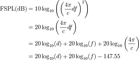
It comes down to a simple physics discussion about free space loss.  The basic equation for free space power loss is:

where:

That formula works for a single frequency, say the carrier frequency, for example. As the signal gets spread out by modulation, the power density on any given frequency is reduced as the energy is divided between many other frequencies.

First, free space loss takes into account the spreading out of electromagnetic energy in free space is determined by the inverse square law, i.e.

\ S = P_t \frac{1}{4 \pi d^2}

where:

  • \ S is the power per unit area or power spatial density (in watts per meter-squared) at distance \ d,
  • \ P_t is the total power transmitted (in watts).

Second, with Frequency Modulation (FM), the power spectral density is a function of the differences in the highest and lowest frequency:

 P=\int_{F_1}^{F_2}\,S(f)\,d f + \int_{-F_2}^{-F_1}\,S(f)\,df.

Therefore, the narrower the bandwidth of a signal, the higher the density of the received signal will be in relation to the transmitted power.  An unmodulated FM signal will have a better, more reliable coverage area than a modulated one.  Of course, we need to modulate the signal, otherwise, there is no point in having the transmitter on.

A baseband or composite FM signal has several components:

FM baseband signal
FM baseband signal

An FM station transmitting a mono signal will have a much lower bandwidth. With wideband FM, the modulation index is generally 2 or two times the maximum audio input frequency. Thus, a mono FM broadcast station will have an approximate deviation of approximately 30 kHz (plus any ancillary services like RDS) vs a stereo FM station, which has a 75-80 kHz deviation using the same carrier power.

For higher power FM stations, FCC Class C and B, this is not much of an issue.  Those stations tend to have a great deal headroom when it comes to power density, building penetration, multipath (picket fencing and capture effect).  For Class A and LPFM stations, it is a different situation.  For those stations,  unless FM stereo broadcasting is truly needed, it should be turned off.  On low power stations, stereo can be a great detriment to reliable coverage.

Developments on the digital radio fronts

I am still in awe of iBiquity and I have to hand it to them for stick-to-it-liveness. The newest “fix” for their FM IBOC system, colloquially known as HD Radio™, is in contour on-channel repeaters.  According to the article “Performance of FM HD boosters varies,” (Radio World online edition), the reason for such boosters is to “increase or fill in FM Digital footprint so that the digital coverage matches that of analog.”

The idea that IBOC is somehow an improvement over FM analog is becoming (or has become) untenable.  In order to make the new system cover the same area with the same reliability as the old analog system, on-channel bandaids boosters are now needed.  And what is with this extending coverage?  How much more expensive will radio station owners have to deal with to make this scheme work?  And I still don’t understand where the improvement over analog-only systems comes from.

As the article points out, however, all is not well in paradise; the IBOC booster signals interfere with analog signals close to the booster transmitter.  This becomes problematic if the receiver is an analog-only device.  As of this writing, most of the radios in this country do not have HD Radio™ capabilities.  Thus, radios that are currently working perfectly well will be cut out and can become useless around these repeaters.

For your reading pleasure, the entire NAB report can be found here.

Try as they may, neither the NAB, iBiquity or Greater Media can supplant the laws of physics.  Then there is that insanity definition floating around:

Insanity: doing the same thing over and over again and expecting different results.

Albert Einstein

FM transmitter site design

We are currently working with one of our clients who need to rebuild an FM transmitter site.   The site is an old house that used to function as a studio.  The transmitters are wedged into various places and the whole place looks like a fire trap.  We are working on moving the transmitters to a new building at the base of the tower and installing all ancillary equipment according to good engineering standards.

The transmitter site design has changed somewhat over the years.  What may have been good engineering standards in the past have changed with newer transmitter designs and needs.  Up until about 1990 or so, most transmitter sites were cooled with outside air.  As such, there was often a “filter room” or “air mixing room” with associated blowers and fans for moving air through the building.  Older sites often had these features built-in as part of the transmitter installation.  WPTR’s GE BTA-25 was a good example of this.

Modern solid-state transmitters are a little more delicate than their older tube-type brethren.  Tubes were designed to run hot and had no trouble with temperatures up to 110 to 120 degrees or so.  Continental transmitters were famous for this.  As Fred Reilly once told me “We’re Dallas and it gets hot here.  The manufacturing floor is not conditioned.  It doesn’t matter, 100 degrees, 105 degrees, they just keep on working.”  I think he was talking about the assemblers as well as the transmitters.

Solid-state transmitter switching power supplies are also somewhat finicky.

A good transmitter site design will incorporate the following:

  1. Good air conditioning.  Calculating the AC load for the transmitter waste heat, other installed equipment, as well as the building solar gain.  Waste heat is a function of AC/RF transmitter efficiency, which is found in the owner’s manual.  If unknown, 50% is a good design standard, in other words, waste heat equals TPO.
  2. Good grounding.  A good grounding system is a must for all transmitter sites.  This includes lightning and RF grounds.  Low impedance paths to a single point ground is a must.
  3. Good power conditioning.  Mountain top transmitter sites are susceptible to all sorts of utility company irregularities.  Surge protection is a must.  Series types are better than parallel.
  4. Good lighting.  Nothing is worst than fumbling around in a half-lit transmitter room trying to make repairs.
  5. Adequate workspaces and clearances.  Electric panels require three feet of clearance from the front.  Cabinet doors should be able to swing fully open.  All-access panels should be, well, accessible.
  6. Adequate electrical system.  Pole transformers and service entrances are properly sized for the load.  Backup power.  Plenty of work outlets around the room.

Some of these may seem like no-brainers, however, one would be surprised at how transmitter sites have grown over the years.  An FM site that may have started with one 5 KW transmitter in 1950 will have been greatly upgraded over the years.  Today, that same site may not employ a 30 KW transmitter, full air conditioning, several tower tenants, etc.

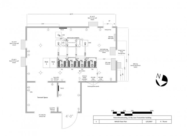
WHUD transmitter site diagram

This is a transmitter site that we redesigned about four years ago.  The original site was built in 1958 and had a Gates FM5B as the main transmitter.  The electrical service consisted of two 200 amp panels which had been greatly altered over the years.  It had an old Onan 65 KW propane generator inside the building.  Grounding, Air Conditioning, lighting, and workspace were all substandard.

The first thing we did was replace the generator with an outdoor unit.  That allowed us to remove an interior partition, freeing up a good deal of floor space.  The next thing we did was upgrade the electrical service and replace the generator transfer switch.  Much of the interior wiring had been altered or added to in non-code-compliant ways.  All of those modifications were removed or bought up to the current electrical code.

A safety grounding ring was installed around the outside of the building and all grounding points were bonded together.  Nautel has an excellent guide for transmitter sites which includes lightning grounding and protection for AM and FM transmitter sites.  Recommendations for Transmitter Site Preparation (.pdf) and Lightning Protection for Radio Transmitter Stations (.pdf) are available for download from their site.  All RF cable outer jackets are bonded to the ground at the base of the tower and the entrance to the building.  All the interior equipment is bonded together.  Ferrite toroids are placed on all cables going into and coming out of the transmitter cabinets.

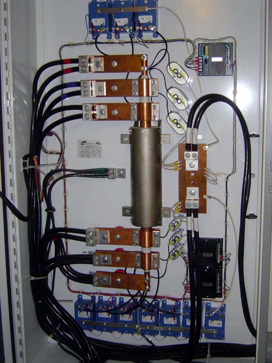
With the electrical service upgrade, we added the series LEA surge protector.

LEA series surge protector
Inside view of LEA surge suppressor

This site as at the very end of the utility company line and has always suffered from power issues.  This unit greatly smooths out the various nasties that get sent our way.

I decided that it was easier to use compact fluorescent lights (CFL) rather than long tubes.  This site is as the top of a rough mountain road and it is simply easier to carry several small boxes in the cab of the truck than four foot or eight foot florescent light tubes.  There is a total of ten 28-watt fixtures in the main transmitter room which light up every nook and cranny.

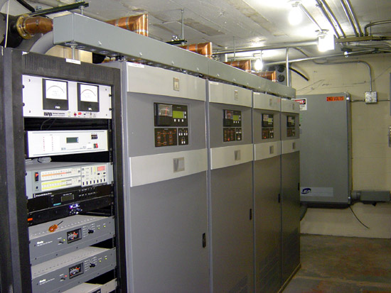
WHUD transmitter
WHUD transmitter

All of the transmitters and electrical panels were laid out to give working room around them.

The air conditioners were also greatly upgraded and added to the generator load.  Prior to this, when the power went out, which was often. the air conditioners did not run and the transmitter room would overheat unless the door was left open.  What we previously the filter room became space for tenant equipment.  There are a few two-way and paging companies still at this site.

Of course, all this work was done while keeping the station on the air as much as possible.  There were a few instances of having to turn off to move transmission lines and so on.

The result of all this work is greatly improved site reliability.