The topic today; Lycorma Delicatula, AKA The Spotted Lantern Fly. These little plant hoppers are native to China and Vietnam and were accidentally imported to the US back in 2013 or so. They were first spotted in Pennsylvania in September of 2014 They are destructive and invasive. Now, found in the Mid Atlantic and Mid Western parts of the United States as well as other areas, they are devastating to native flora. In upstate NY, the grape industry is being especially hard hit.
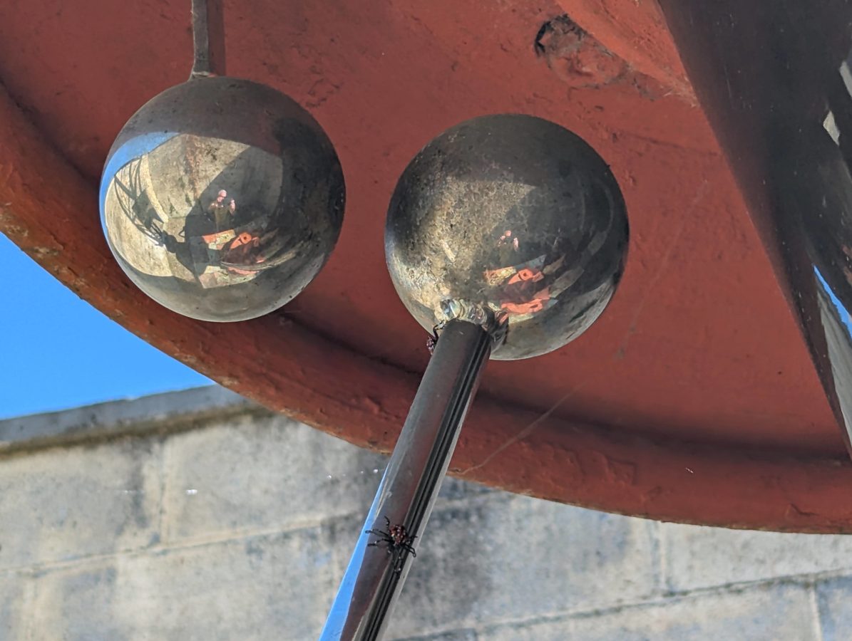
So, what does this have to do with broadcasting? Great question. Recently, on one of the AM sites we take care of, I noticed several VSWR trips during the late afternoon. Coincidentally, a landscaping company came and chopped all the vegetation around the tower base. That is when I saw it. These little things were crawling up to the ball gap and getting zapped.
Spotted Lantern Fly Nymph crawling on ball gap
The best and only course of action when finding these things is to terminate their existence with extreme prejudice. I have a few grape vines around the homestead and I found that making them hop off an land in the grass is the easiest way to kill them. For some reason, the grass tends to make it difficult for them to hop away. The female bugs are larger, so I tend to concentrate on those first.
They have few natural predators in the US, although that seems to be slowly changing. There are a couple of fungi that seem to kill them and birds such as Robins are discovering them. Eventually, they will find their place in the food chain and become less of an issue. Hopefully, that happens sooner rather than later.
This post is about a Large Loop On Ground (LLOG) receive antenna.
I have, for some time, been lamenting the demise of my K9AY antenna last year. While I don’t spend a lot of time Shortwave Listening these days, it is sometimes a nice diversion on a rainy day.
I have been reading about LOG (Loop on Ground) broadband receive antennas for a few years and the concept sounds interesting. Loop antennas in general, tend to reject RF noise better than dipole or vertical ground plane type receivers.
The idea is the loop antennas are more H field (magnetic) than E field (electrical) receivers. Most unintentional RF noise generators create noise in the E field.
Near Field vs. Far Field Electro-Magnetic energy
Additionally, close proximity to the ground further lowers E field noise due to capacitive coupling with the ground. The ground acting as a sink for the E field noise. Loops also tend to have better rejection of chaotic Near Field energy. Thus the combination of those three things will create slightly lower signal with much better signal to noise ratios over traditional up in the air antennas.
The downside is that it cannot be used for transmitting. The capacitive coupling noted above will quickly dissipate all of the transmitted RF into ground as heat.
The LOG antenna that most amateur radio operators use is either or close to the antenna outlined by Matt, KK4JY: The Loop on Ground Antenna
That is all well and good, but I want something larger to go down through the entire Medium Frequency band in into Low Frequency range. The main reason is I want to start fooling around with the 2200 and 630 meter amateur radio bands. Also, wanting a good low noise AM broadcast receive antenna. With that in mind, I began taking inventory of available real estate and parts.
As for real estate; I own a patch of woods behind my house that is approximately 200 x 200 feet. Good enough for a fairly large square loop. The good thing about particular plot of land is it is far away from the neighbors, the utility lines and other sources of electrical noise.
As for the available parts; it turns out I had almost everything needed. The only thing I needed to purchase is a water tight outdoor enclosure for the matching transformer, from Amazon for $9.00.
Here is a list of items used:
Item
Amount
Use
Comment
Cost if new
Wire, 14 AWG
470 feet (143.26 M)
Wire Loop
Pieced together from left overs
$100.00 (500 ft spool) at Home Depot
Toroid, BN-73-202
1
Transformer core
Left over
$0.95 at Amidon
Wire, 26 AWG magnet wire
18 inches (46 cm)
Transformer winding
Left over
$9.00 (2 oz) at Amazon
Coax Cable, Cablewave FCC38-50J
175 feet (53.34 M)
Transmission line to house
Salvaged from decommissioned AM directional
$53.00 (500 ft spool RG-6) at Home Depot
RF Connector, type N Female
1
Antenna output
Found in junk drawer
$6.00 (6ea) F chassis mount at Amazon
Enclosure, ABS water tight IP67
3.9 x 3.9 x 3 inch (9.9 x 9.9 x 7.62 cm)
Transformer housing
Purchased from Amazon
$9.00 at Amazon
The wire is copper THHN 14 gauge. If buying new, this is the single largest expense. I soldered and heat shrunk several lengths from left overs on spools. This antenna is going to be in the shade, so I don’t have to worry too much about UV degradation of the insulation. If that happens, I can find some more insulated wire.
The big bonus is the Cablewave FCC38-50J phase stabilized cable, most of which is buried out to my old K9AY antenna, I simply extended it about 50 feet. Having the line already buried to much of the manual labor out of the project. The buried section of line acts as an RF choke, fully eliminating any electrical noise coming from my house at the antenna side of the line.
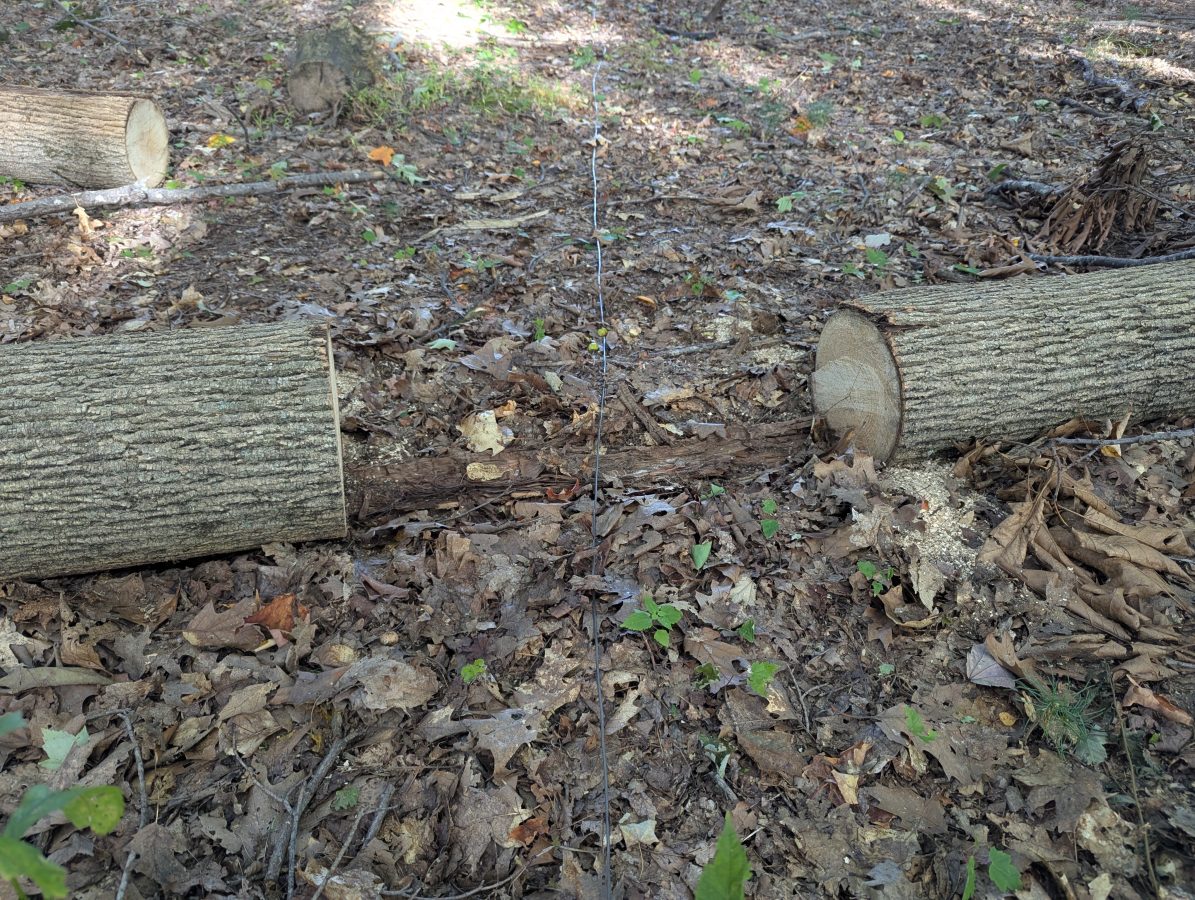
Large Loop On Ground antenna, installed in woods behind my house
I did have to go around and clear away some brush and dead trees along where the antenna wire was laid on the ground. I wanted to make sure that the wire was directly on or within an inch or two of the ground.
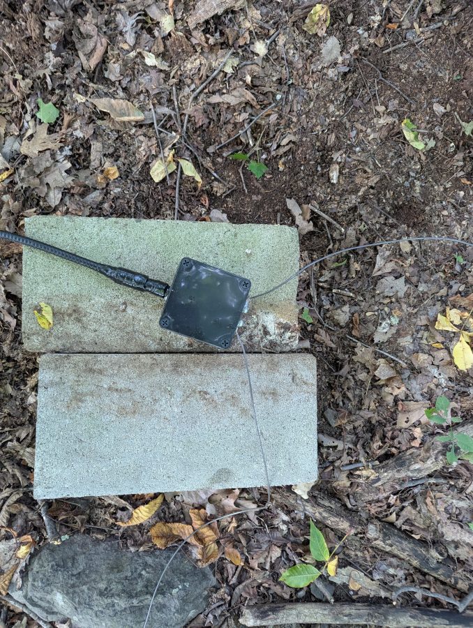
LLOG antenna transformer and transmission line
The transformer took about 20 minutes to construct. It consists of six windings on the antenna side and two windings on the transmission line side. I used a type 73 core because I am more interested in the medium frequency range. It seems to work well up to about 15 MHz. The transformer is for galvanic isolation, keeping the loop current balanced and separated from the transmission line. The shield is not grounded at the antenna side, but is grounded where it comes into the house. On the transformer enclosure, I used a salvaged N connector to match what I had for the transmission line. Any low loss cable, including RG-6 or RG-11 will work very well.
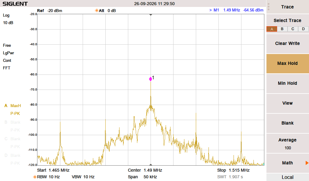
WKNY signal, 18 miles distant from transmitter
After a few hours of low intensity work, I had everything together. I connected the antenna to my trusty Kenwood R-2000 receiver and tuned to the nearest Class C AM on 1,490 KHz. Wow! What a difference! This little 1 KW high band station 18.6 miles (30 km) away barely came in before, especially when the ground is dried out. The relative signal strength meter on the receiver shows an S9+5. I am located on the edge of the predicted 0.5 mV/M contour while the spectrum analyzer shows a -65 dB signal, which is netting a 44 dB SNR, which is very good. All of this is after a Mini Circuits ZSC-4-2 power divider, which has an insertion loss of -6 dB per port.
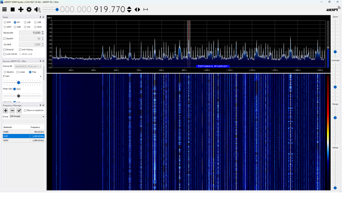
Wide view of the entire AM band, about 1pm
One of the reasons for the “decline of AM;” overcrowding. This was taken during the daytime, when there was no skywave propagation. Barely an open frequency.
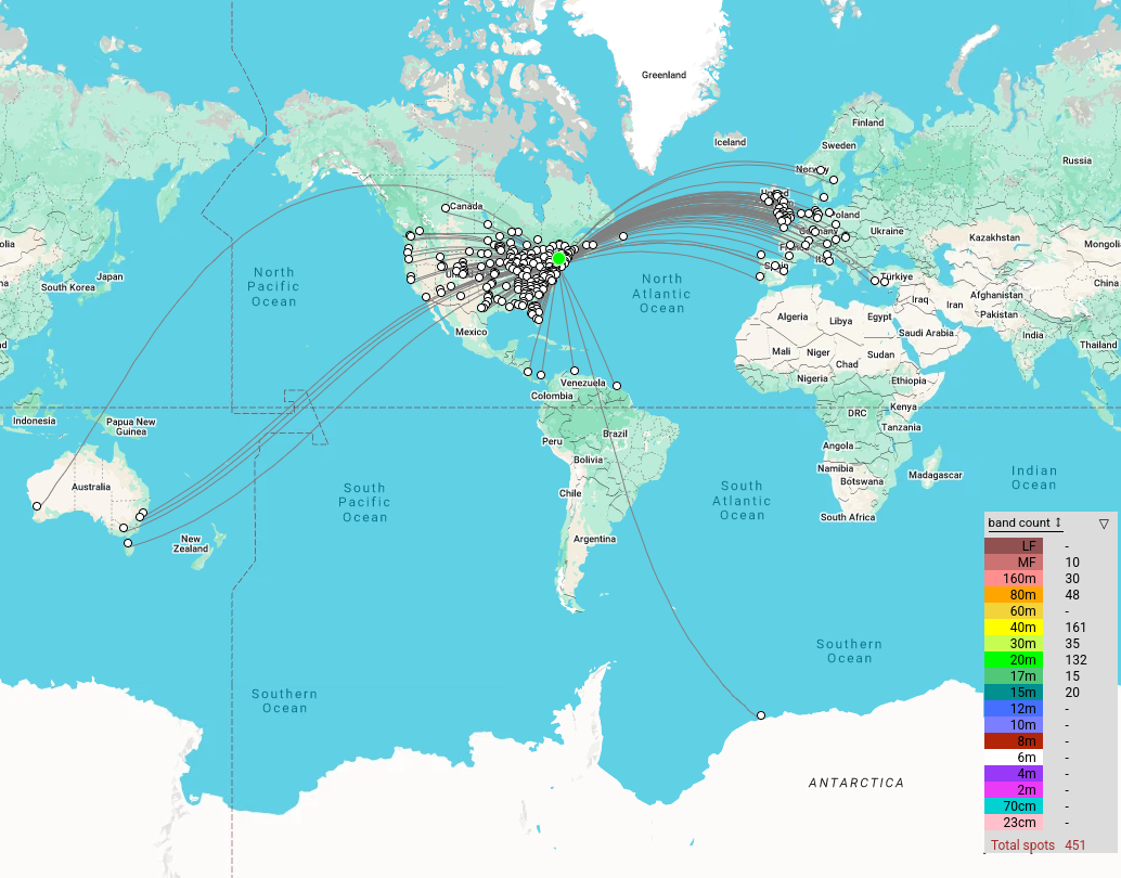
With the spectrum analyzer and made a few interesting discoveries. First, the noise floor in the Medium Frequency range goes from about -100 to -110 depending on the frequency. The noise floor on High Frequency is -112 or lower across the entire band. I clearly get all of the NYC AM stations as well as most of the stations in and around Albany. Before sunrise, I tuned around the 630 (472 to 479 KHz) meter band and heard a few stations sending CW (W4TS @ 164 miles (264 KM), K2ORS @ 157.2 miles (253 KM)). A few overnights of WSPR monitoring on 475.6 KHz netted 194 spots from 11 different stations. The furthest was 822 miles (1,322 KM) away in central Illinois. All of these stations are transmitting 5 watts EIRP or less.
LLOG 72 Hour WSPR reception map
This antenna works well to about 15 MHz, where the signals start to drop off because of the transformer material that I used.
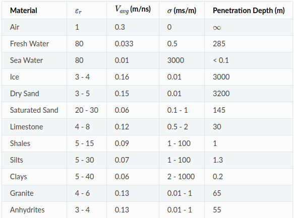
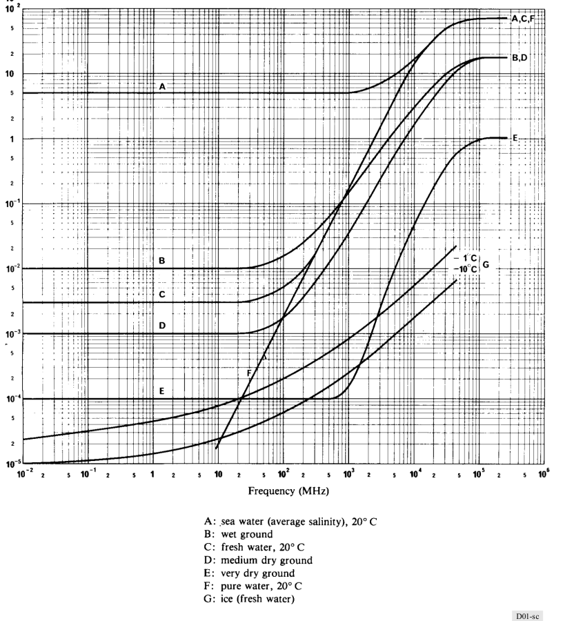
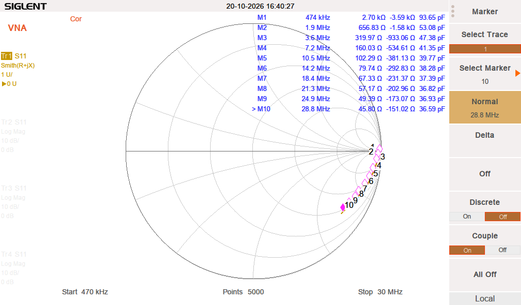
Using the Network Analyzer, I found the resonance is 2.865 MHz with a -36 dB return loss. This makes sense, as the wire laying on the ground will have a lower velocity factor due to the capacitive coupling with the earth. In this case the VF of the antenna is 73% when the soil is dry. The velocity factor should go down when the ground gets wet, or covered with snow.
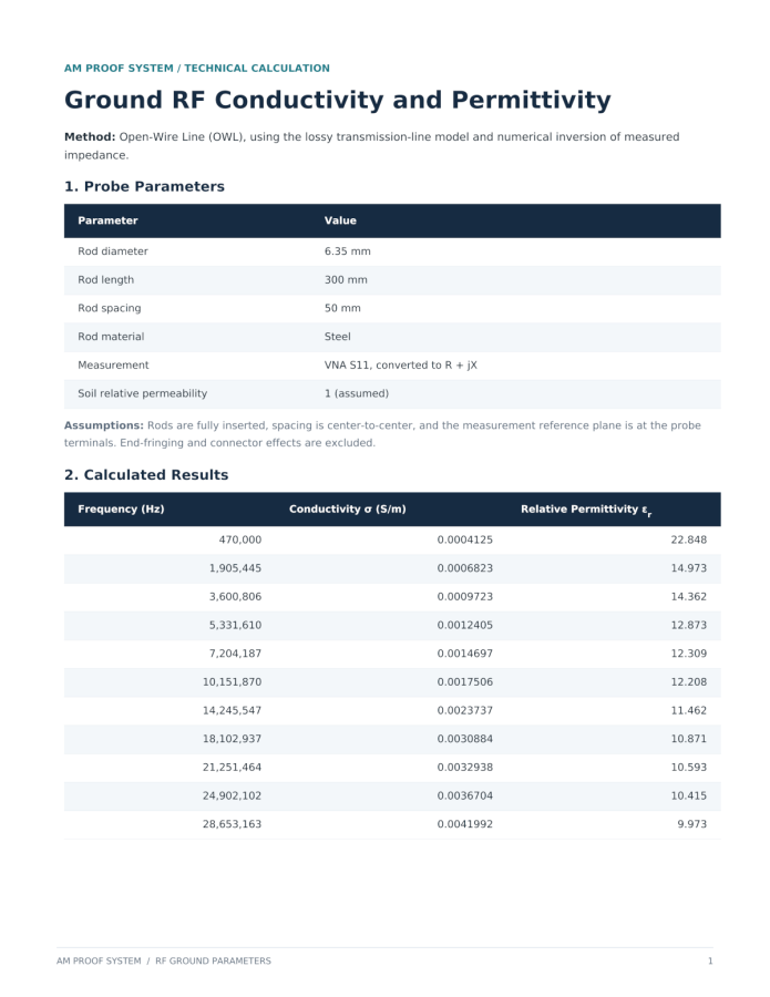
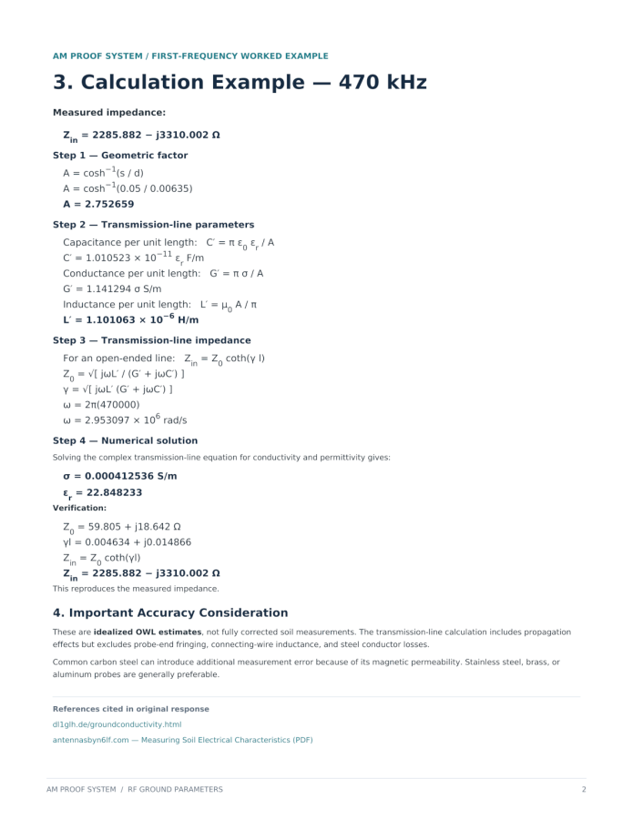
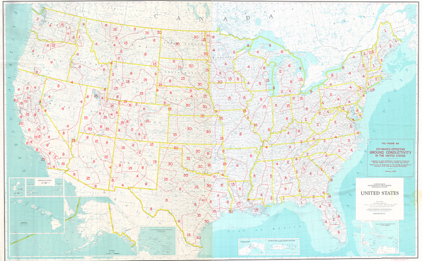
It might be interesting to do some ground conductivity measurements…
First of all, I have received a few off line questions about my well being due to the absence of posts recently. I assure you, I am fine. I am really busy with a variety of projects, most of which cannot be blogged about due to restrictions from station owners.
Secondly, I hope that all are staying safe in this current heat wave, which is effecting a large part of the country.
Finally, my country is celebrating its 250th birthday. In my youth, I was lucky to have traveled around many areas in Asia. It was an eye opening experience because I was not visiting tourist destinations. It made me thoroughly understand how important our constitution is. That experience also taught me how important it is to take action and participate in governance.
How?
Vote.
Voter apathy has lead to some of the worst election outcomes in history. In New York City, Zohran Mamdani received 573,000 votes in the primary and 1,114,184 votes in the general election. In the 2025 New York City Mayoral election 2,174,547 people cast a vote. There are 4,960,233 active registered voters in New York City. That means that 43% of registered voters showed up and 22% of registered voters elected Mamdani the Commie. That is a problem; 22% is not a mandate under any system, yet here we are.
If you think your vote doesn’t count, you are wrong. If you do not like the candidates, register for a party and vote in the primary. If you think you can do a better job, run for office. There are many ways to become meaningfully engaged in the election process. Go (or watch on line) town board meetings. Ask questions, call your local representatives and so forth.
A story about skirted AM towers and Cellular carriers.
Skirted AM tower with cellular equipment
We take care of a few sites that have skirted AM towers with Cellular equipment installed. For the first few years, all was well. The cell carriers put up their equipment under supervision and we made sure that the AM station’s antenna still was working when the were finished. At some point, things changed.
Stiff arm hitting skirt wire
It is a little bit hard to see because the camera is focused on the foreground and not the background, but the stiff arm from the cell carrier sector is shorting the skirt wire to the tower.
More often then not these days, tower crews show up unannounced and start working on the tower. I had a call from a client their station being off the air only to arrive on site and find a crew on the tower with the AM skirt grounded by a set of battery jumper cables. The ground crew said they kept getting shocked by the wire so they grounded it.
In other cases, they show up, do the work and leave before anybody notices. Then, at some point somebody checks the AM transmitter readings and sees a problem.
AM skirt wire, shorting against mounting bracket
In another situation, the tower crew came and installed new equipment. They installed an insulating sleeve around the skirt wire (while the transmitter was on) but did not secure it well enough. The eventually, sleeve slipped down the wire and it shorted. No one, not even the tower owner, knew about the tower crew being on the tower.
AM skirt wire insulating sleeve
Same tower, the sleeve on this wire rotated around so that the opening was facing the stiff arm causing a large charred, melted plastic area.
These were repaired with some left over coax-seal and electrical tape. After this, I was able to retune the ATU using my network analyzer.
The only solution, it seems, is to put up more cameras with motion detection notification so when somebody shows up unannounced the station will at least know about it.