Here in the northeast, there are seasonal variations in the types of weather phenomena encountered. Blizzards in the winter, severe thunderstorms, and the occasional tornado in the summer, at least that is the way it normally happens. This year, we have already had two thunderstorms and a stretch of unusually warm weather. My highly advanced personal weather prognostication technique consists of looking at trends, and the trend thus far this year is warmer with more storms.
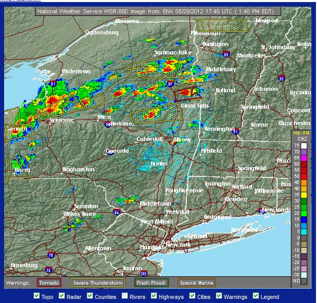
Weather Radar, thunderstorm line
When the weather RADAR looks like this, it is too late.
To that end, it is time to go around and check all of the grounding and lightning suppression methods at various transmitter sites and studios. I would rather spend a few minutes extra now than get called out in the middle of the night for an off-air emergency related to a lightning strike.
Proper grounding of all equipment, RF cables, and electrical service entrances is the minimum standard for transmitter sites. Proper grounding means a common point grounding system connected to one ground potential.
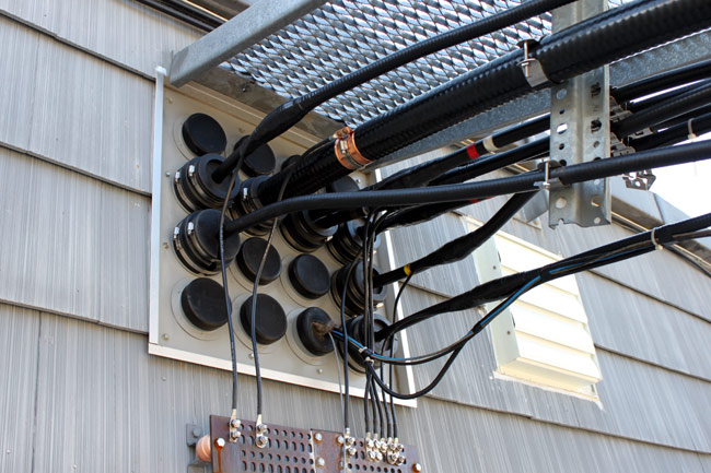
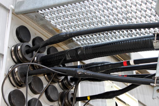
To that end, all coaxial cables that enter the building need to have their outer shields bonded to the site grounding system at the base of the tower and the entrance of the building. With an FM station where the antenna is mounted at the top of a tall tower, the coaxial cable outer jacket acts as an insulator along the length of the tower. A lightning strike on the tower will induce a very high potential on the outer conductor of an ungrounded transmission line. After entering the building, the lightning surge will find the next path to ground, which will likely be a coax switch or the transmitter cabinet. Neither of those two outcomes is desired.
Thus, it was time to ground the transmission lines at WRKI, the FM transmitter we moved last January.
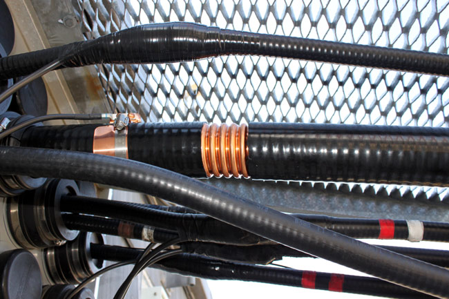
3 inch coaxial cable grounding kit
Fortunately, Andrew, Cablewave, Dielectric, and others make grounding kits for various size coaxial cables. They are very easy to apply and make a solid connection between the outer conductor and the site ground.
3 inch coaxial cable grounding kit
The kit contains a copper band bonded to a ground wire, stainless steel clamp, waterproofing, tape, and a pair of bolts.
3 inch coaxial cable properly grounded
The concept of transmitter site grounding is pretty simple and inexpensive to implement. Thus, it is surprising to me how many transmitter sites, especially older sites, do not have adequate grounding. That is an accident waiting to happen.
I found this on one of the guy wire anchor points for a 400-foot tower:
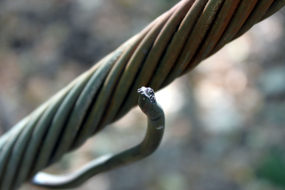
#2 solid copper wire burned open by a lightning strike
Had to be a pretty big hit to burn open a #2 wire. This is on one of six guy anchor points for the tower. The ground wire is U-bolted to each guy wire before the turnbuckle and then goes to ground. This was noted between the last guy wire and the ground rod.
It is important to find and fix these things, as the next lightning strike on this tower would have a less-than-ideal path to ground at the guy anchor points, forcing the current to flow through other parts of the transmitter site, possibly through the transmitter itself, to ground.
I generally try to do a brief inspection of towers, guy anchors, lighting, painting, and a general walk around the property twice a year. That helps prevent surprises like “Oh my goodness, the guy wires are rusting through,” or “Hey, did you know there is an illegal “hemp” farm on your property?” Well, no officer, I don’t know anything about that…
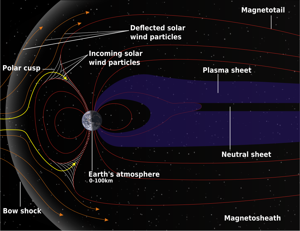
By now, you have heard of the great solar flare of 1859 that set telegraph wires afire across the US and Europe. This phenomenon was due to a large electromagnetic pulse from the earth’s magnetosphere interacting with the particles from a Coronal Mass Ejection (CME) caused by the solar flare. The long stretches of wire suspended above the earth acted like a large generator winding and cutting through the magnetic field, which in turn caused voltage (Electromagnetic force or EMF), which in turn, caused the fires.
In 1859 our understanding of electricity and magnetics is not what it is today, thus, the fires were likely caused by overloaded conductors without means to bypass excess electrical energy to ground.
Schematic of Earth’s magnetosphere, courtesy NASA
Fast forward to today. We are in the upswing of solar cycle 24, which is expected to peak in May of 2013. NASA predicts that this will be the lowest sunspot peak since 1907. That does not necessarily mean the coast is clear. Over the last 11 years since solar cycle 23 peaked, computers and electronic automation have proliferated exponentially, becoming the norm. Things like GPS not only guide clueless travelers where to turn but also sync up all those cellular telephone transmitters with timing signals. IP networks, SCADA, telephone networks, and so on all run on some form of CPU. Newer Energy Star appliances like toasters and refrigerators also have CPUs. That technology has yet to experience a large electromagnetic pulse (EMP) in the real world. Things could indeed get hairy if a moderate to large class X solar flare generated a CME that was polarized correctly to interact with Earth’s magnetic field and cause damage at ground level.
Solar flares and CME are slow-moving events, with 1-2 days warning before the effects of a CME reach Earth. One can stay apprised of solar flares and other solar activity by subscribing to NOAA Space Weather Prediction Center’s email service.
HEMP Mechanism for 400 kM high altitude burst
Of greater concern is other sources of EMP like high altitude nuclear explosions (HEMP). Those types of events, while rare, can happen. The good news is, the defense mechanisms for solar flares, high-altitude nuclear bursts and lightning-induced EMP are the same. They are effective grounding, shielding, filtering and surge suppression.1 Of the three EMP scenarios, high altitude nuclear burst has the tightest design spec, so creating a building that incorporates the ideas in MIL-STD-188-125-1 specifications is a good start.
The question becomes, is all of this really necessary. It depends on how important it is to radio station ownership to remain on the air during such an event. Based on historical information and global geopolitics, the probabilities of such an occurrence are:
Lightning strike – 1:1 Any radio station that has a tall structure, particularly a steel tower, will get struck by lightning, perhaps several times per year depending on the region.
Large Class X solar flare resulting in damaging CME – 1:21 Since 1859, there have been seven solar flare events that have disrupted communications or power systems on Earth. This is a bit misleading since 6 of the 7 events have occurred in the last 22 years, making the real probability more like 1:3.6
High Altitude EMP – 1:30 Based on seventeen high altitude tests carried out by the US and USSR in 1962, the growing nuclear proliferation and a June 2005 Reuters article “Experts warn of substantial risk of WMD attack” in which the author stipulates a thirty percent risk of a nuclear attack of any type in the period of 2010 to 2015.
EMP Theory
High altitude nuclear burst EMP has three components; the fast component (20/550 ns pulse) is an electromagnetic shock-wave, the medium-speed component (1.5/5000 μs pulse), and the slow component (0.2/25 s pulse) resulting from the expansion of the explosion’s fireball in the Earth’s magnetic field.1 Compare that to a lightning strike, which typically has a 1.8 µs rise time. That means the first pulse frequency is from about 72 to 200 MHz, the second pulse frequency is from about 800 Hz to 2.5 MHz and the third pulse is basically DC and affects mostly long wires. Thus, any shielding, grounding and suppression needs to consider the highest frequency down to about 10 KHz.2
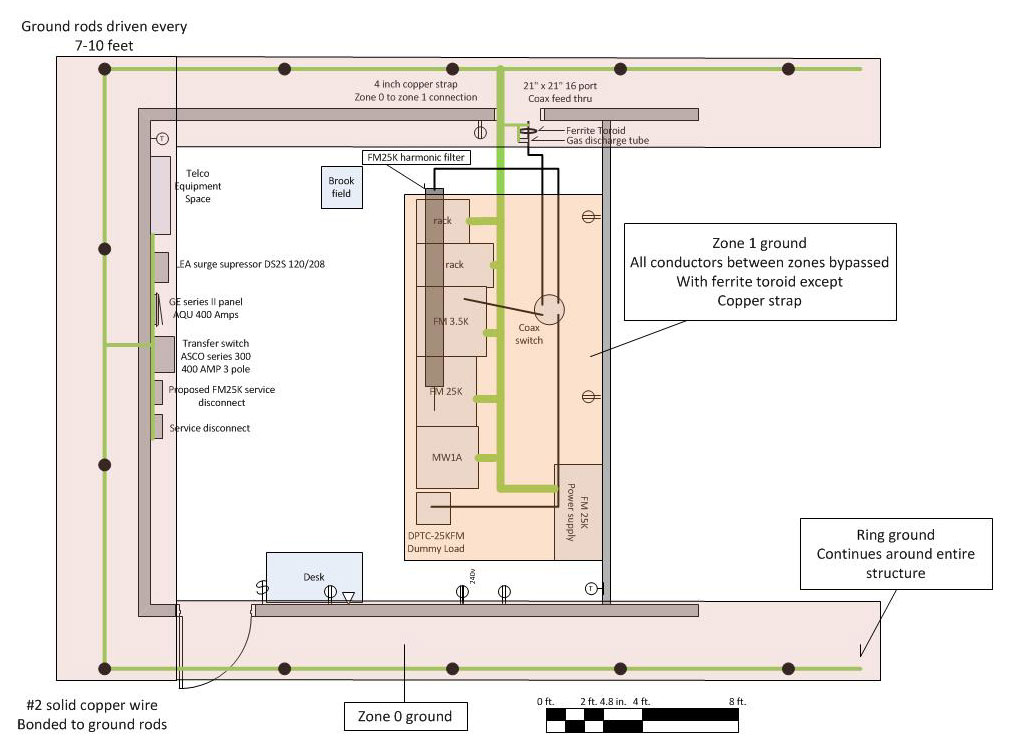
The rise time to frequency comparison is an important consideration in the design and construction of grounding systems. Grounds need to present the least amount of inductance possible. This means using solid, not stranded wire, keeping bends to a minimum and where required, use long radiuses. Bond all junctions by welding, exothermic welding or soldering. Use a single point ground system. Zone grounding should also be employed. The definition of zone grounding is concentric grounding areas connected to each other by a single low-inductance ground conductor.2 The idea of isolating grounds by use of a ferrite suppressor may seem odd, however, if there is a separate RF ground, tied together with the building ground using wide copper strap laid on the floor, this will minimize ground system “reception” of incoming EMP.2,3
Zone grounding diagram
Shielding means surrounding the protected equipment with a conductive material such as copper plate, aluminum plate, copper mesh, aluminum mesh, brass mesh, steel plate or steel mesh.1,2 There are advantages and disadvantages to each. Seams should be welded to prevent “leaks.” Doors need to have finger stock or metal compression gaskets to ensure proper sealing of opening. Other openings for ventilation, cable ingress, etc. need to be “significantly” less than one wavelength. MIL-STD-188-1 gives the allowable opening size of 10 x 10 cm or 3.9 x 3.9 inches. If openings in the shield become greater than approximately wavelength/6 meters (at 250 Mhz, about 8 inches), significant fields can penetrate to the interior.2
Suppression deals with those connections to the areas outside of the facility. These include incoming electrical service, data service and RF transmission lines to and from antennas. Since the fast component of the HEMP falls within the VHF spectrum, FM broadcast installations are particularly vulnerable. Suppression devices for incoming AC power are readily available from commercial sources and are well proven. LEA makes a series surge suppressor that uses a combination of fast acting silicone diodes, MOVs, and an LC filter made up of series inductance and parallel capacitance to ground. The LEA DYNA family series surge protectors have a system response time of less than one nanosecond and are tested to greater than 1,000 operations.4 The response time depends on a good, non-inductive ground connection.
LEA DYNA systems series surge protector
Suppression for incoming RF and data cables is more difficult because the normal operating frequencies fall within the HEMP rise time frequency. Incoming data at a transmitter site usually consists of a DS-1 circuit however, larger capacity circuits are sometimes used. Fiber optic cables are immune from HEMP as they have no metal conductors. Copper data lines must have a data line surge suppressor between the TELCO demark and the CSU.
RF cables must have their shields ground to the zone 0 ground, then go through a ferrite toroid to add inductance to the outer shield and isolate it from the zone 1 ground. After the ferrite toroid, a gas discharge type inline surge suppressor should be used. These come in a variety of configurations, frequency band and power levels. It is best to keep the suppressor rating as close to the peak carrier power as possible, affording the most protection to the transmission equipment.
Design and implementation of EMP hardened facilities
Of the four strategies for mitigating HEMP; Grounding, Suppression, filtering and shielding, shielding is the hardest and most expensive to implement. Good grounding should be included in any good radio station design same as suppression and filtering.
Grounding. Grounding for a transmitter site must include an outside ring ground around the periphery of the building.2 This is bonded to several ground rods installed at regular intervals. The ground is brought into the building and all coax shields, electrical service entrance, TELCO equipment, suppression equipment and safety grounds are connected to it. This forms the zone 0 ground. One conductor then goes to the zone 1 ground which is the transmitters and racks. Any other conductors at any potential that go from zone 0 to zone 1 are bypassed at EMP frequencies by use of ferrite toroids or other high mu ferrous metal filters. Inductors may need to be bonded to ground to prevent saturation. At studio locations, the building electrical safety ground should be evaluated for adequacy. Additional grounding may need to be installed depending on effectiveness of existing ground. Any outside antennas, supporting structures, satellite dishes and generators need to be bonded together and grounded to the building electrical grounding system. Studios and engineering rack rooms need to be bonded to the ground using star topology. Facilities that are not adequately grounded should be retrofitted.
Suppression and filtering. Good surge suppression and filtering should be a part of all transmitter and studio site designs. Hanging a few MOVs off of the service panel is not enough to prevent damage to a facility. All incoming lines from the street; electric, telephone, and cable need to have surge suppression connected and be bonded to a low inductance path to ground. The only exception to this is fiber optic, which is immune to the effects of EMP. Additional layers of filtering for sensitive, mission-critical computer systems such as FERUPS, shielded category wiring that is properly installed, etc. Facilities that do not have adequate suppression can be retrofitted.
Shielding. Shielding is the most expensive, time-consuming, and difficult to install correctly. The High Altitude nuclear test Starfish Prime in July of 1962 produced a field of 5600 V/m in Honolulu, some 1300 KM away from the blast. Building a shielded structure against those intense magnetic and electrical fields is very difficult. Attenuating the field through layers of shielding is the most effective means provided the distance between the shields is wavelength/6 or more (about 27 inches at 72 MHz) to prevent coupling.2 For example, using a concrete structure with steel mesh creates 35-40 dB of attenuation in zone 0, and a well-designed transmitter with good RF shielding in its cabinet design creates a shield for zone 1. Equipment racks can also be used to create shielding zones by using copper or brass mesh with good metal-to-metal contact around the front and back doors. At studio locations, engineering rack rooms should have copper or brass mesh embedded in the wall structure to create a shield. This will create a safe area to locate computer file servers, routers, switches, STL gear, satellite receivers, and the like equipment. Layered shielding with the use of metal, gasketed door will improve shield performance. Retrofitting shielding is more difficult to accomplish than grounding and suppression. It is best done in new construction. There are many different ways to accomplish even moderate shielding, which may serve well for lightning and solar flare-induced EMP.
From personal experience, investing an extra $10-20K in grounding and suppression at a lightning prone transmitter site in Florida solved all of the issues at that site. Prior to installing the ring ground and bonding, the transmitter was knocked off the air several times per year. Since the work was done in 2005, there has not been one lightning related outage at that site.
References: 1. Protection Technology Group, System Approach to EMP Mitigation, February 2011 2. US Army Corps of Engineers, Engineering and Design – Electromagnetic Pulse (EMP) and Tempest Protection for Facilities EP 1110-3-2, December 31, 1990 3. US Department of Defense, HIGH-ALTITUDE ELECTROMAGNETIC PULSE (HEMP) PROTECTION FOR GROUND-BASED C4I FACILITIES PERFORMING CRITICAL,TIME-URGENT MISSIONS, MIL-STD-188-125-1A, February 15, 1994 4. Protection Technology Group, Modular Hybrid Series Connected Surge Protection Device LEA DS21 data sheet, 2010
The rumble of thunder this morning let me know that lightning season is upon us here in the Northeast and likely the rest of the country as well. I used to enjoy the odd summer thunderstorm, especially the late afternoon pop-ups that cool off a hot summer’s day. Now whenever I see lightning or hear thunder I wonder if the phone is going to ring. Chances are good that it will not, as I invested many hours of my time and my previous employer’s money into lightning protection at the transmitter sites.
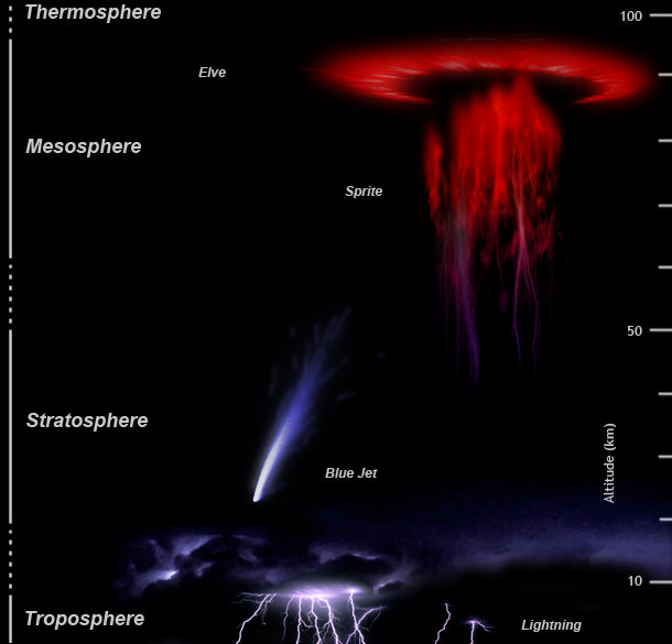
upper atmosphere lightning depiction
I go on the assumption that all tall steel towers will get struck, oftentimes repeatedly, during any particular electrical storm. Back in the day, I took a course by Polyphaser called “The Grounds for Lightning and EMP Protection.” It was a great primer on how to ground and bond equipment at a transmitter site to eliminate current flow, which is the cause of all EMP and lightning-induced failures. When I was in military communications, no expense was spared as they took uptime very seriously. Any downtime was a personal affront to the commanding officer of the unit in question.
Lightning is DC however, it behaves more like 10 KHz – 2 MHz AC. Therefore, lightning and EMP grounding systems need to be designed and installed to accommodate DC through 10 KHz AC voltages. This is easily done by choosing the correct conductors, ground bus bars, and bonding systems.
The other path lighting takes into a transmitter is through the AC mains. Utility company high voltage primary feeds act like large antennas for lightning-induced EMP. Fortunately, much of that is filtered out by the step-down transformers just before the building service entrance. It is still possible, however, for some impulse voltage to make it through the transformers and into the service entrance panel. On older tube type transmitters, this could often damage the plate voltage power supply because of the voltage multiplication factor of the plate transformer. Oftentimes, the transformer secondary would have “holes” punched through the insulation to ground. This is an expensive and time-consuming repair.
I would conservatively estimate that for every $10.00 spent on lightning protection, $1,000.00 dollars worth of damage and downtime is saved. Overall, a pretty good return on investment.
The basics for lightning ground bonding are thus:
Use the lowest inductance wire possible. The industry standard is #2 solid copper, however, if bonded properly, there will be very little current flow inside the transmitter building, so if #2 is not available, then any solid wire up to #8 will work. Tower ground bonding should be as heavy as possible.
Ground all guy anchor points, and bond all guy wires together and to the same ground rod or ground rod system.
Keep the bonding conductors as straight as possible, bends should be long sweeping turns to minimize series inductance.
All metal equipment should be bonded, no rack, telco demark, electrical panel, dummy load, bulkhead entrance grounding bus, combiner, door frame, etc should be left unbonded.
All coax outer shields should be grounded where it comes into the building.
All coax cables should go through a toroid before being connected to the transmitter.
All outdoor bonding connections should be exothermically (CAD welded) bonded to ground rods.
All grounding must go to a common ground point, AKA star grounding point. No individual ground points should be allowed in the building.
Multiple ground rods were installed around the outside perimeter of the building as deeply as possible. Some mountaintop transmitter sites may require special grounding material (Bentonite) and or to have a ground well drilled. Ground conductors should have as much surface area contact with Earth as possible.
The whole idea is to present a low-resistance ground path and keep all of the equipment at the same potential to minimize the current flow between equipment.
For the electrical building service entrance, a series surge protector installed before the service panel is the best method. Several are made and they need to be sized for the building service. A fallback is a parallel surge protector that will provide some protection. On the AC mains connections, any series inductance that can be added to increase resistance to the lightning pulse is good. All AC mains connections to the transmitter should go through a toroid before they are connected to the transmitter. This is a good idea for remote control and mod monitor wiring as well.