The Crown FM2000A transmitter

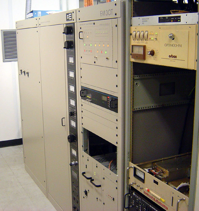
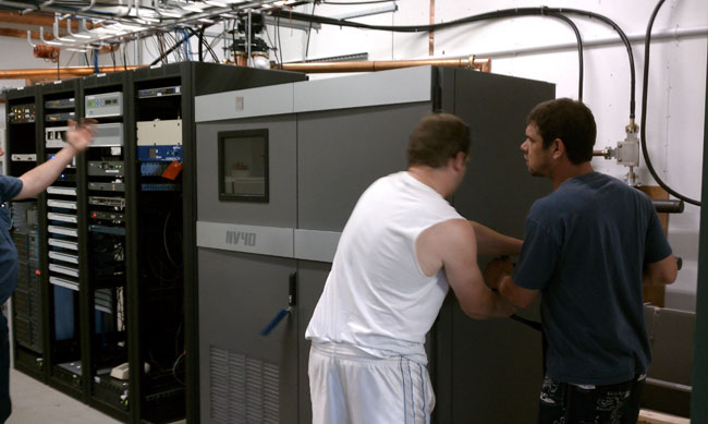
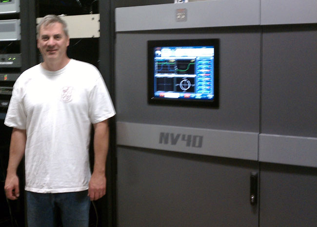
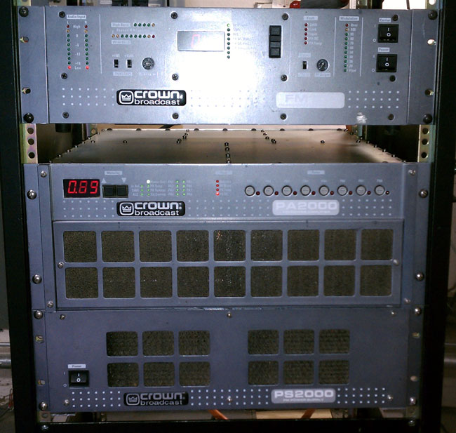
I had the opportunity to work on one of these recently, thought I’d post a few observations.  The transmitter itself comes in three parts, the FM100 which serves as the exciter and driver, the PA2000, which holds the RF amplifiers and combiner and the PS2000 with supplies the DC voltages to run the PA.

Crown FM2000A transmitter running at half power

That configuration has some advantages and disadvantages. First, it takes up much more rack space than the comparably powered Nautel VS2.5.  Second, because the unit does not come with slide-out rack rails, each part needs to be removed from the rack for servicing, which makes things a little difficult when working alone as the PS2000 weighs quite a bit.  As far as the rest of the design, the PA2000 is very modular, all of the PA modules, controller card, fuse board, and RF combiner easily come out of the chassis for service.

Crown FM2000A top cover removed

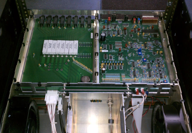
This unit had been in service at WBEC in Pittsfield, MA for an undetermined amount of time. As such, there was quite a bit of dirt and bugs inside the PA chassis. I used an air blower to clean everything out. Checked the fans for bad bearings, checked all RF connections for signs of overheating, etc.  I also cleaned out the power supply and rinsed all of the air filters.

Crown FM2000A front cover off

My other minor complaint is the power adjust pot is under the front cover.  When making adjustments and such, the LED display indicates operating constants based on a little LED light next to the display.  The legend is on the cover, which has been removed to adjust the power.  Minor thing, but slightly annoying, nonetheless.

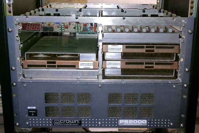
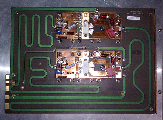
There are four RF modules in the PA2000, each one generating 500 watts.  This particular transmitter has a bad device in PA3.  When the transmitter is running the DC fault LED flashes and the PA3 reading shows no current.  The device is a BLF278, which is a fairly common, inexpensive RF MOSFET.  According to the factory tech, they can be replaced in the field provided one can solder.  After replacement, there is no special tune-up or anything needed as the module is wide-band.

Crown PA2000 500 watt RF module

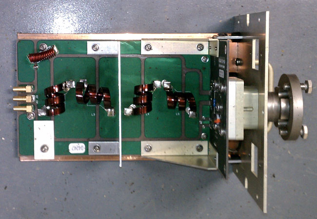
The four modules are combined and then sent to the RF output filter which has the low pass harmonic filter and directional coupler.

Crown PS2000 output combiner
Crown PS2000 output filter

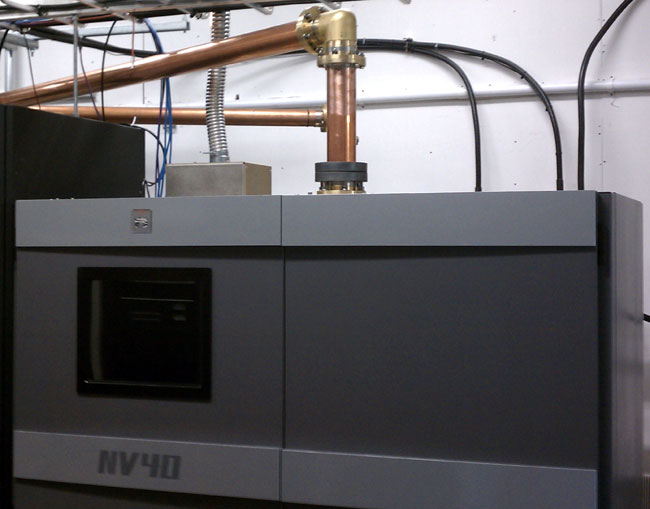
It is a pretty simple transmitter, no bells or whistles or fancy things like IP connectivity.  Overall, it seems to be well-made, robust, modular, and efficient.  The remote control interface is via DB-25 connector on the back of the PA2000.

I did not get a chance to hear it on the air, I was just cleaning and testing the RF sections.  The exciter is an FM100 transmitter, which I had to change frequencies on.  I found that to be self-explanatory.

It would be fun to compare this to some of the other broadband FM amplifiers like PTEK and Armstrong.

The Nautel VS-2.5 FM transmitter

This is cute. A small (VS allegedly stands for “Very Small”) integrated 2,500-watt FM transmitter.  This one we just finished installing as a backup transmitter for WSPK, on Mount Beacon, New York.

Nautel VS-2.5 FM Transmitter

This site has a Nautel V-7.5 as the main transmitter.  That unit is very reliable, however, this transmitter site is non-accessible 4-5 months out of the year due to ice and snow.  The last time we had an off-air emergency due to a crippling ice storm, it took an entire week to clear away all the downed trees so we could gain access to the site via snowmobile.  As such, every system needs dual or even triple redundancy.  The lack of said redundancy has led to several prolonged outages in the past.

WSPK signal flow diagram

Last year, we were finally able to install a backup antenna after 63 years without one.  This year, it is time to upgrade the rest of the backup equipment.  The new auxiliary transmitter is connected directly to the auxiliary antenna via a five-port coax switch.  This allows for the use of the dummy load for testing when we are present, but removes a potential failure point in the coax switch.  There have been at least two incidences of the disk jockey accidentally transferring the transmitter into the dummy load when taking transmitter readings.  Hopefully, this configuration will be fairly idiot-proof.  I am making an interlock panel that will prevent both transmitters from being on the air at the same time.

Nautel VS 2.5 connections

This site is a work in progress.

The backup processor is at the transmitter site, the main processor is in the rack room at the studio.  This works well because the main processor occasionally looses its mind and needs to be rebooted.  It would be a significant pain to drive all the way up to the transmitter site just to reboot the processor.  It might not happen at all during the winter.  The backup processor has no mind so it is not an issue.

The VS transmitter is attractive because it has a built-in exciter that accepts composite, AES, or IP audio.  The exciter also has a built-in Orban processor as an option.  Thus, if it really hit the fan, we could use the LAN extender to get the audio to the site.  Further, it could be addressed by any studio in the company WAN.  Which is cool, when you think about it.

Nautel continues to crank out innovative, dependable products and there is nothing wrong with that.

Tube transmitters vs Solid State transmitters

I thought it would be interesting to do a comparison between the two types of transmitters, both AM and FM.  I have been doing this thing for 25 years and have quite a bit of experience working on all types of transmitters.  Some of the broadcast transmitters I have personally worked on over the years include:

  • Harris: FM-20H, FM-5G, HT-35, HT-10, HT-3.5, FM-25K, FM-5K, Z5-CD, MW-50A, MW-50B, MW-1A, MW-5A, BC-5H, SX-5, SX-1A, Gates 1
  • Broadcast Electronics: FM-5B, FM 3.5A, FM5A, FM30A, FM35A, FM30T, FM20T, FM10S, FM5C, FM1C, AM10A, AM6A, AM5E, AM1A
  • Continental Electronics: 816R-2, 814R-1
  • Collins Rockwell: 831F-1, 838E-1
  • Nautel: ND-1, ND-5, XL-60, V-40, V-10, V-7.5, NV-40
  • Gates: BC5P, BC1T, FM5B
  • General Electric: BTA-25
  • RCA: FM20ES1, BTA5J, BTA1-AR
  • CSI/CCA, Visual, Energy Onix, Bauer, McMartin, QEI, some Italian something or other, etc.  Various makes and models.

I think I have a fair amount of transmitter experience under my belt.  What I have found is that certain brands of transmitters are better than others, regardless of whether they are tube or solid-state.  There are several differences in each type, obviously.  As to some blanket statement about which is better, solid state or tube, I don’t have one.  My statement would be “It depends.”

Tube transmitters are more rugged and will take more abuse than a solid-state unit. Things like heat, lightning, EMP, and mismatched antenna won’t phase a well-designed, well-manufactured tube transmitter.  On the other hand, they are less efficient AC to RF, have higher B+ voltages, have hard failure modes, and are more difficult to linearize, if that is required for some reason.

Solid state transmitters are more broad-banded, easier to change frequency, they have soft failure mode due to redundant amplifiers and power supplies. The voltages are lower, thus they are safer to work on.

Here is a complete list of advantages and disadvantages of each type:

AttributeTubeSolid StateComment
RuggednessVery rugged, able to take heat, EMP, lightning, mistuned antenna, poor operating environment, etcNot heat tolerant, lightning and EMP can damage MOSFETS, switching power supplies sensitive to AC mains issuesAdvantage: Tube
Electrical EfficiencyLess efficientMore efficientAdvantage: Solid State, however efficiency gain can be wiped out due to larger air conditioning requirement
Failure modeHard, most oftenSoft, most oftenAdvantage: Solid State, failure of a single module or power supply generally will not take unit off the air
Frequency agilityDifficultEasyAdvantage: FM Solid state transmitters can easily be moved.  AM transmitters still require extensive retuning.
Re-occurring costMoreLessAdvantage: Solid State, as tube changes are required every two to three years
MaintenanceSameSameAdvantage: neither
ServicingRequires skilled engineers to service and trouble shootModules and power supplies are often hot swappable and returned to manufacture for repairAdvantage: Solid State, however either type requires occasional measurements with specialized test equipment
Servicing safetyHigh voltages, contact will be fatalLower voltages, but can still be fatalAdvantage: Solid State
RedundancyLowHighAdvantage: Dependant on TPO, Higher powered solid-state transmitters are much more expensive than there tube type counterparts
CostLessMoreAdvantage: Dependant on TPO, Higher powered solid state transmitters are much more expensive than there tube type counterparts
AvailabilityGood used market, some new FM transmitters still being builtGood new and usedAdvantage: Tube
 Reliability Dependent on brand Dependent on brand Advantage: neither

For some reason, the latest Broadcast Electronics tube-type transmitters seem to have very long tube life.  I installed an FM20T at WYJB in Albany, New York,  in early 2001 and it is still on the original tube, some ten years later.  The same can be said for the 2005 FM20T and FM30T installation at WHHZ/WKZY, Gainesville, Florida.   Those tubes show no sign of giving up anytime soon.  I don’t know if that is an unusual trait of the transmitter or that particular tube.

WKZY, Gainesville, Florida

The above comparison seems to heavily favor a solid state transmitter.  As a general rule, brand new solid state transmitters both AM and FM have advantages in almost every category except high power FM transmitters, where tube types still make sense.  From a used transmitter standpoint, there is nothing wrong with a tube type transmitter, provided it has a solid state IPA.  I have noticed the 4CX250B driver tubes most often used in FM IPA stages have markedly reduced reliability of late.  I would also tend away from transmitter makes and models where the manufacture is no longer in business or no longer supports the product.

New Nautel NV-40 at WVPS, Burlington, VT

Sorry for the prolonged absence. I have been, quite literally, out of reach for the last two weeks. In fact, for the entire month of July, I spent just five days at home. Some of the travel was for work and some for pleasure.

On the work side of the equation, WVPS in Burlington, Vermont has a new Nautel NV-40 transmitter.  WVPS is the NPR affiliate for Vermont Public Radio and it’s transmitter site is located on top of Mt. Mansfield, in Stowe, VT.  I will do a separate article about the Mt. Mansfield transmitter site because it is an interesting place.  WVPS is a Class C FM on 107.9 Mhz.  They have one HD subchannel for the VPR classical music format.

The Nautel NV-40 transmitter is greatly updated from the V-40, which was installed at WHUD.  Basically, the V-40 is four ten-kilowatt transmitters combined.  It is a novel approach and offers quite a bit of redundancy as entire transmitters can be switched off and worked on with the other three remaining on the air at full power.

The NV-40 is a single large chassis with internal combining networks.  It uses different RF modules but the same power supplies.  The entire thing is controlled by a fancy GUI on the front of the transmitter but also has the ability for manual control if the GUI fails.  That is a key feature not seen in other transmitters which simply won’t work without the fancy computer.  Other things that I like, are the ability to control all of the biasing and other options via the GUI and things like a spectrum analyzer and Lissajous display.  The ability to look at several graphic displays at once makes it easy to configure and monitor.

The transmitter arrived at the top of the mountain via a local moving company.  After unloading it on the loading dock, it took some amount of doing to get it down the hall into the transmitter room.  The thing weighs in at 1,600 pounds after being uncrated.

Nautel NV-40, Mt. Manchester transmitter site loading dock
Nautel NV-40, Mt. Mansfield transmitter site loading dock

Unpacked:

Nautel NV-40 uncrated and read to move down the hallway

Moving into the final position in the WVPS transmitter room.

Movers putting transmitter into final location and removing pallet jack

The connections were made to the transmitter, including connecting grounding strap to the back, 200 amp electrical service and the RF output connection via 3 inch rigid coax.

Nautel NV-40 installed

The remote control consists of basic transmitter functions going to a dial up Gentner remote control and a Network connection going to the GUI.  The network connection allows persons on the network to use a web browser to look at the GUI.  The HD radio connections are made via a HD radio importer and exporter, located at the studio, which also uses the network, via a connection on the exciters, to send the HD subchannel.  The analog main channel is via an AES/EBU connection from the STL.

All connections go through large toroids to help isolate the transmitter from any lightning-related surges.

Before I left, we tested it at full TPO into the dummy load.  All worked well, the only outstanding issue was getting the HD radio importer/exporters to work over the network, which was out of my jurisdiction.

Author and Nautel NV-40

Here is a rather blurry picture of your author standing next to the NV-40 with the exciter and GUI turned on. There are to IEC power connectors at the top of the transmitter that go to the GUI and exciters. This allows those part of the transmitter to run on UPS’s, which is nice, being that the GUI takes about a minute to boot up after power failure.