Repairing the Nautel VS2.5 transmitter

The newish Nautel VS2.5 transmitter installed at WJJR had an RF module failure. This particular model transmitter does not have slide-in RF modules as other Nautel transmitters do.  To fix this transmitter, it has to be pulled out of the rack, flipped over, and opened from the bottom. The module replacement is very straightforward, there are five solder pads that connect to wires carrying the input, output, power supply, and bias voltages.

Nautel VS2.5 transmitter RF modules and combiner

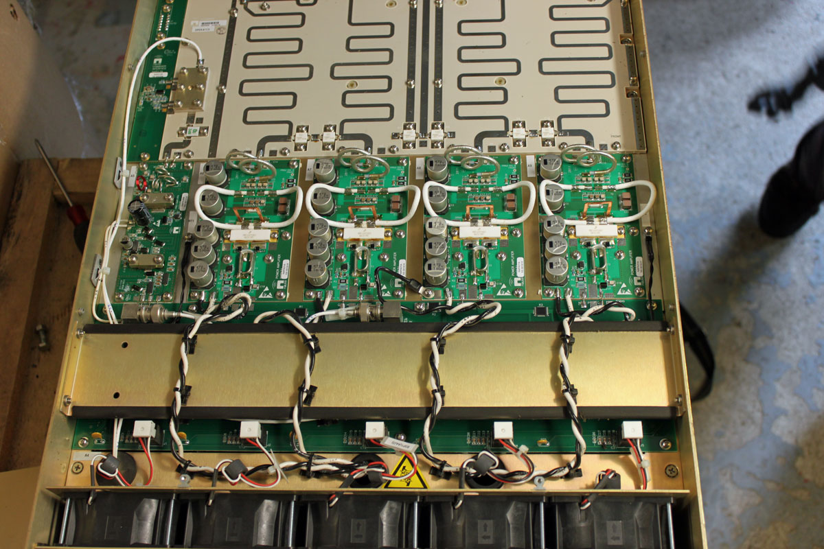
The troubleshooting guide gives good instructions on how to check the PA MOSFETS with a DVM. I found that 1/2 of the device in PA1 was bad:

Schematic Diagram, NAPA31

All in all, not a very hard repair. This was under warranty, so a replacement RF pallet was sent to the station without charge. The problem is more about where the transmitter is located:

Killington Mountain, Killington, VT

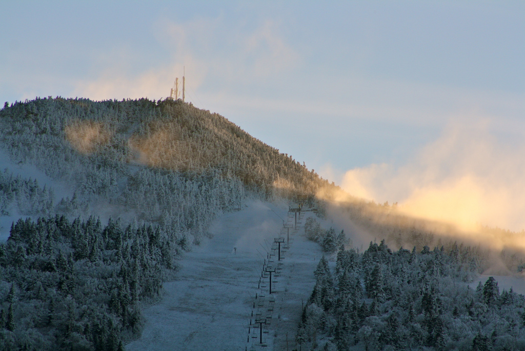
Killington Peak is the second tallest mountain in Vermont, topping out at 4,235 feet (1,291 meters). In the winter, one can take the chair lift to the top. In the summer, the road is drivable with a four-wheel drive. In those in between months, access to the top can be very tricky at best. We had a pretty wet spring this year, so the roads up the mountain are just now becoming passable for vehicles.

Even after reaching the parking lot, there is still a 10 minute walk to the peak, another 200 or so feet up a steep, rocky trail.

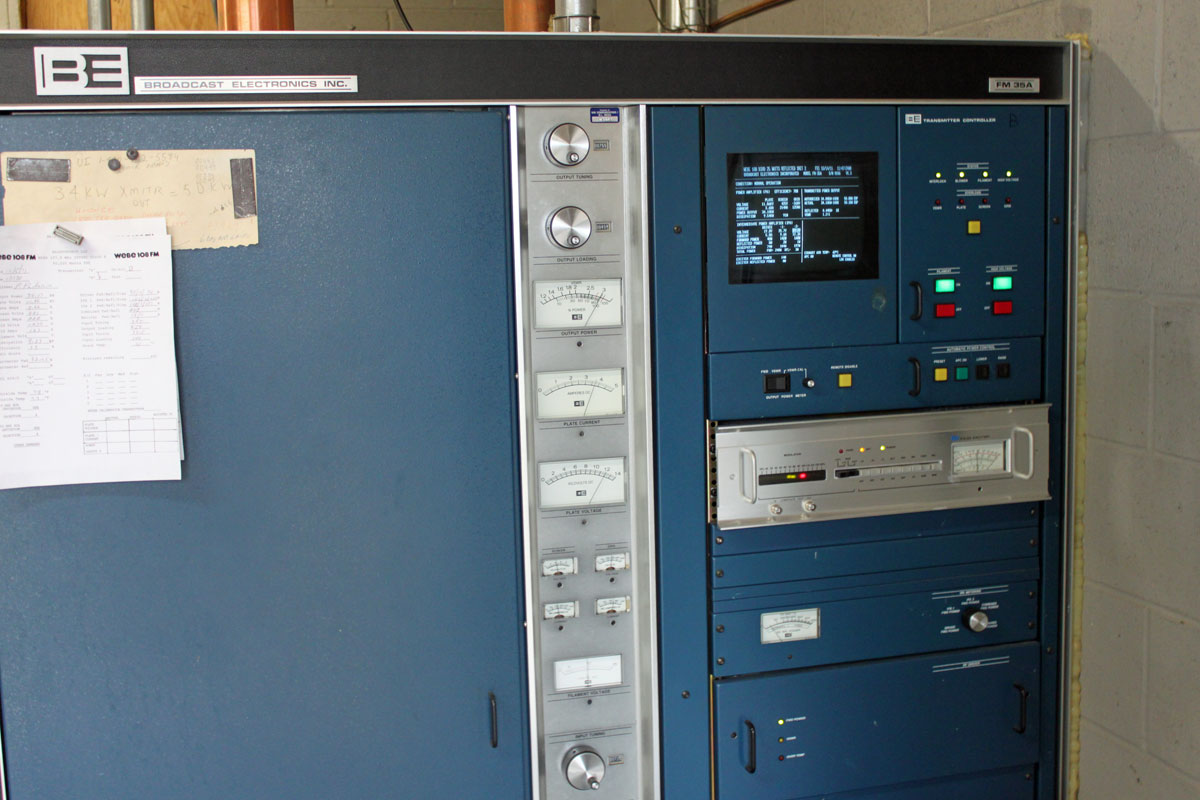
Further complicating things, this transmitter is wedged into this little shack, which holds; a BE FM3.5A transmitter (defunct WJJR), a Harris HT3 transmitter (WZRT), an ERI combiner, two racks of equipment (STLs, Exciters, remote controls, etc) a backup QEI transmitter, an Onan generator transfer switch:

Killington Peak fire tower, WJJR WZRT transmitter building

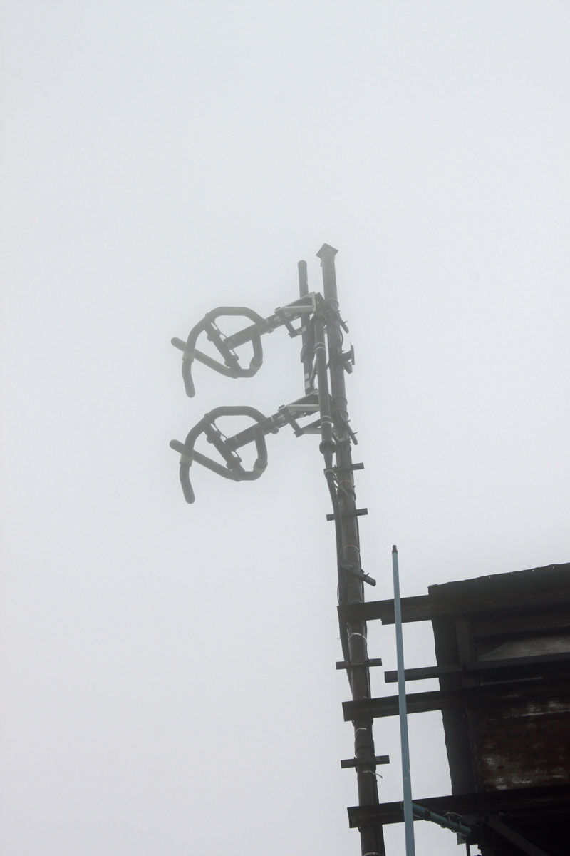
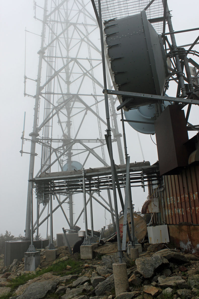
Both stations run into this ERI half-wave spaced antenna:

WJJR WZRT ERI antenna

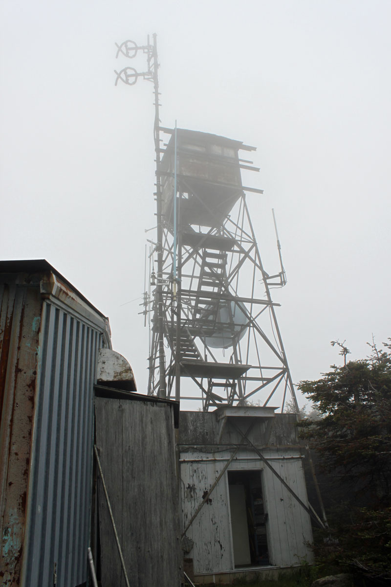
It is very tight in this transmitter room. There is a new tower on Killington Peak, which is still under construction. At some point, the plan is to move into the larger building next to the new tower.

Killington Peak tower

On a clear day, the view from the top is spectacular. On this day, the peak was in the clouds, so not so much:

Killington Peak view

It is a great site, the HAAT is 2590 feet (790 meters) and the stations carry forever on relatively low power outputs.

Failed High Voltage Contactor

This contactor was used to replace the Furnas contactor installed as original equipment when the transmitter was manufactured in 1986.  Furnas is no longer in business, thus the ABB A145-30 was substituted. It was purchased directly from Broadcast Electronics for an FM35A transmitter:

ABB A145-30 contactor

It was installed about 18 months ago and has been in nearly continuous use since.  The broken white plastic housing surrounds the contactor coil and is responsible for pushing and holding down the contact fingers.

ABB A145-30 contactor coil cover

Looks like the coil is running too hot and damaging the plastic. This resulted in a failure of the contactor to make and no high voltage to the transmitter PA.  Obviously a problem.  I spoke to BE about this and they did not have a good answer.  Actually, what they said was “That contactor is rated for 220 amps,” which is true enough. The only thing that I can think of is the coil is rated for 208 volts and the transmitter is connected to a 240-volt delta service.

A new contactor was ordered and installed yesterday.

I will investigate the coil voltages further, but for now, the 27-year-old transmitter remains on the air.

Broadcast Electronics FM35A

Exploding Parts

We or rather, I have been working on installing this CCA transmitter as a backup unit at one of our sites. It was installed as a backup at another site but was mothballed about ten years ago. Now, we need to get it running again and re-tune it. Seems like a fairly uncomplicated job.

CCA FM-5000DS transmitter, circa 1971

Except, every time I start it, another one of these 1000 pf bypass/feed-through capacitors fails. They are located at various points around the PA enclosure and route AC voltages into and out of that enclosure.  The bypass function is needed to keep stray RF off of the control circuits. Normally, they have been failing with a medium resistance fault (40-70 ohms) to the case.  That causes the control circuit breaker to trip.

This time, however, it was on the primary for the filament transformer on the IPA tube.  Just a wee little pop, followed by some ozone smell and sans power output.  I have, thus far replaced four of these and there are seven originals still in the transmitter.

Feedthru capacitors
Feedthru capacitors

It is time to replace them all, otherwise, this rig will fail when we need it the most.  The replacement part is a Mouser 800-24437X5S0102MLF, 1000 pf 500 v made by Tusonix Electronics.