I like these types of posts. Many people are intimidated by component-level repairs. I write this to show that it is possible, with minimal test equipment and easy-to-understand directions, to make repairs and get things back in working order.
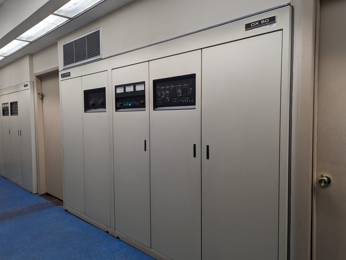
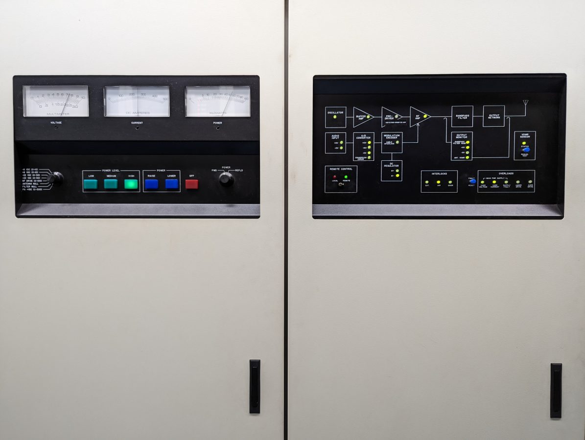
Every year, we lose two or three RF amplifier modules from the DX-50s. Normally, this happens after a thunderstorm. Sometimes it is a spontaneous failure.
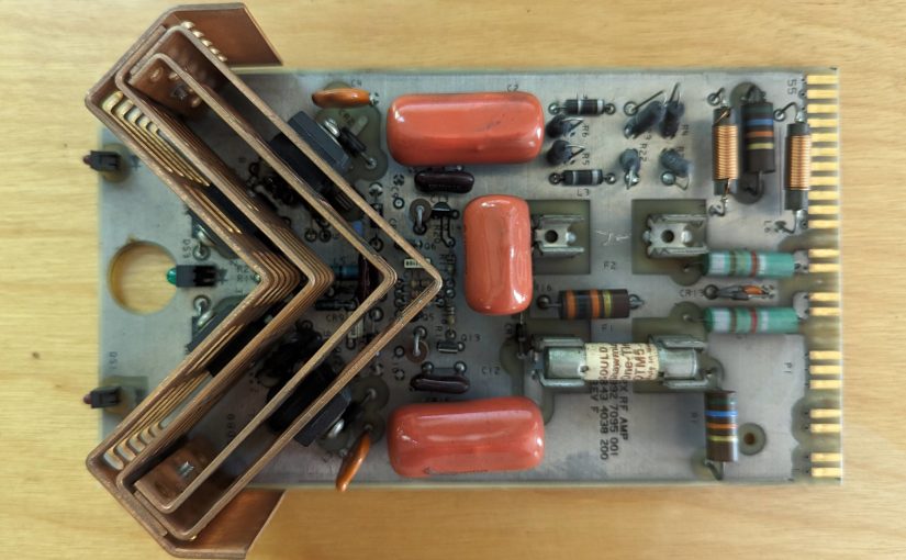
These are fairly simple medium-wave RF amplifiers. There are no adjustments or tuning circuits on the amplifier board itself. They use eight IRFP-350 RF devices. There are two fuses to protect the transmitter power supply against device short circuits. If a fuse blows; Section C, RF amplifier Modules, of the DX-50 manual has a good troubleshooting guide. There is a very good chance that one or more of the RF devices is bad. Unfortunately, they have to be removed to be tested.
Gates Air recommends that if one device is failed, all four devices from that section are replaced at the same time even if they test good. The IRFP350s are inexpensive devices and it is easier to replace everything at once. The Mouser Part number is 844-IRFP350PBF and they are $3.81 each as of this writing. The PBF suffix means it is lead-free.
The other part that can be bad, but it is unlikely, is the TVSS diode across the gate and source (CR1-4). These are inexpensive as well. Mouser part number is 576-P6KE20CA and they are $0.38 each. It is good to have a few of these on hand.
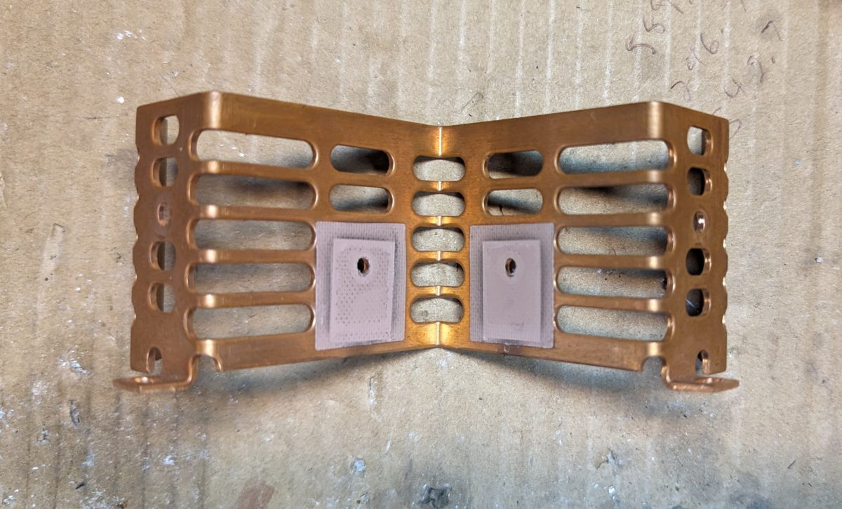
The most difficult part of this is dealing with the heat sinks. The devices get stuck to the heat sink pads after so many years, so it takes a little effort to get them separated. The manual recommends gently prying the device away from the heat sink with a small screwdriver. They can be reused if you are careful and do not rip the insulator pad. However, if the insulator pad rips, it needs to be replaced. Mouser part number 739-A15038108 ($0.86 each).
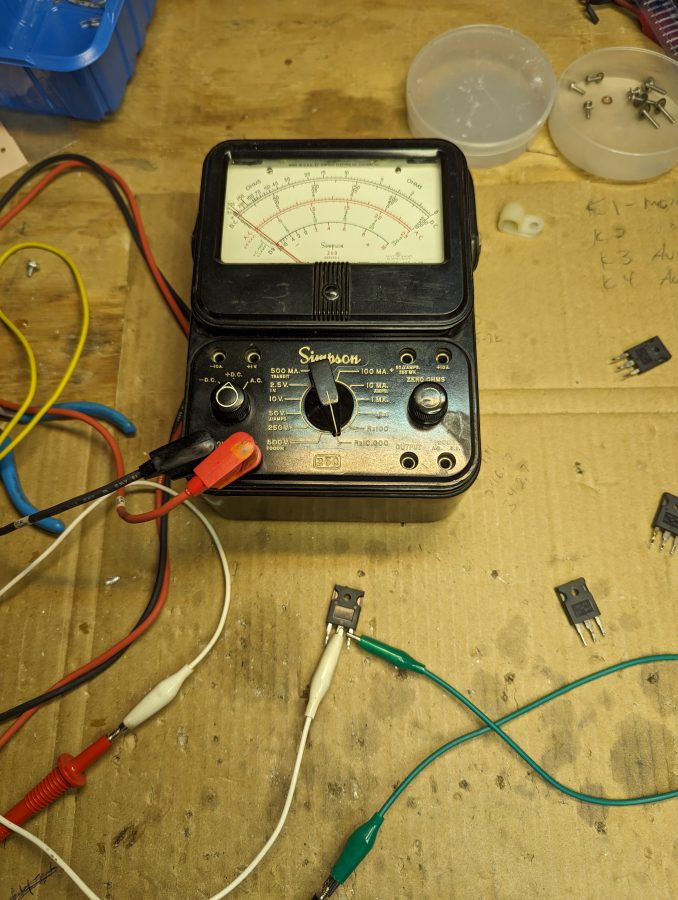
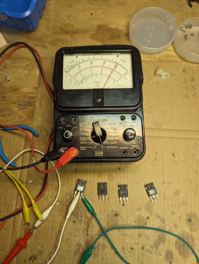
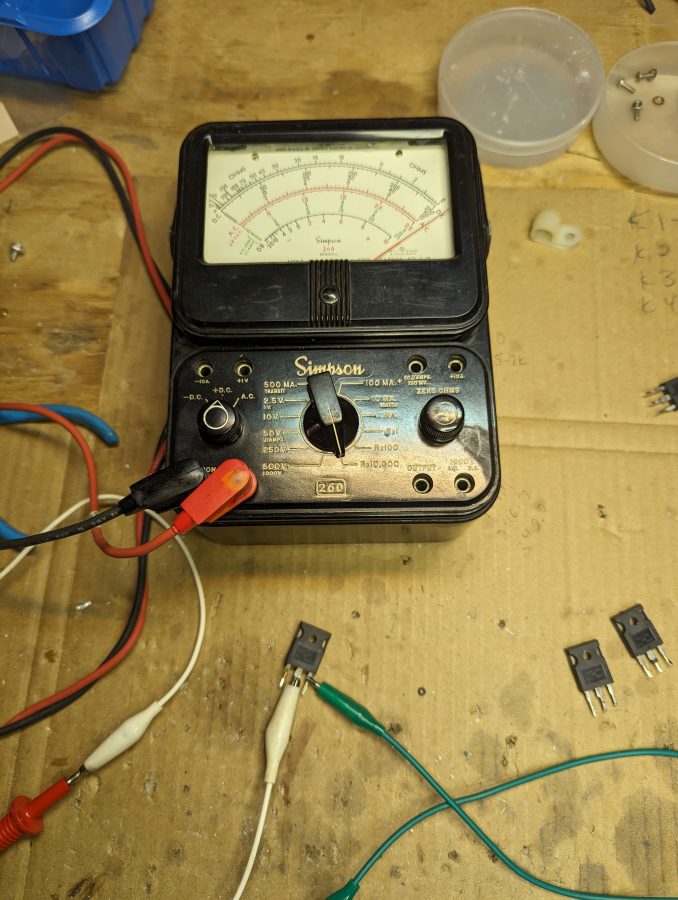
To test each IRFP350 after it has been removed, use either a DVM with greater than 3 VDC on the resistance setting or a Simpson 260 on the Rx10,0000 range. Connect the positive lead to the Drain, the negative lead to the Source, and then use a jumper connected to the Gate to turn the device on or off. Alternatively, you can use a 9-volt battery to turn the device on and off.
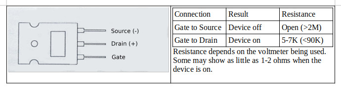
If the device does not turn on or off, it is defective.
The TVSS diode should measure open (>2M) in both directions. Anything other than that, the unit is defective and needs to be replaced.
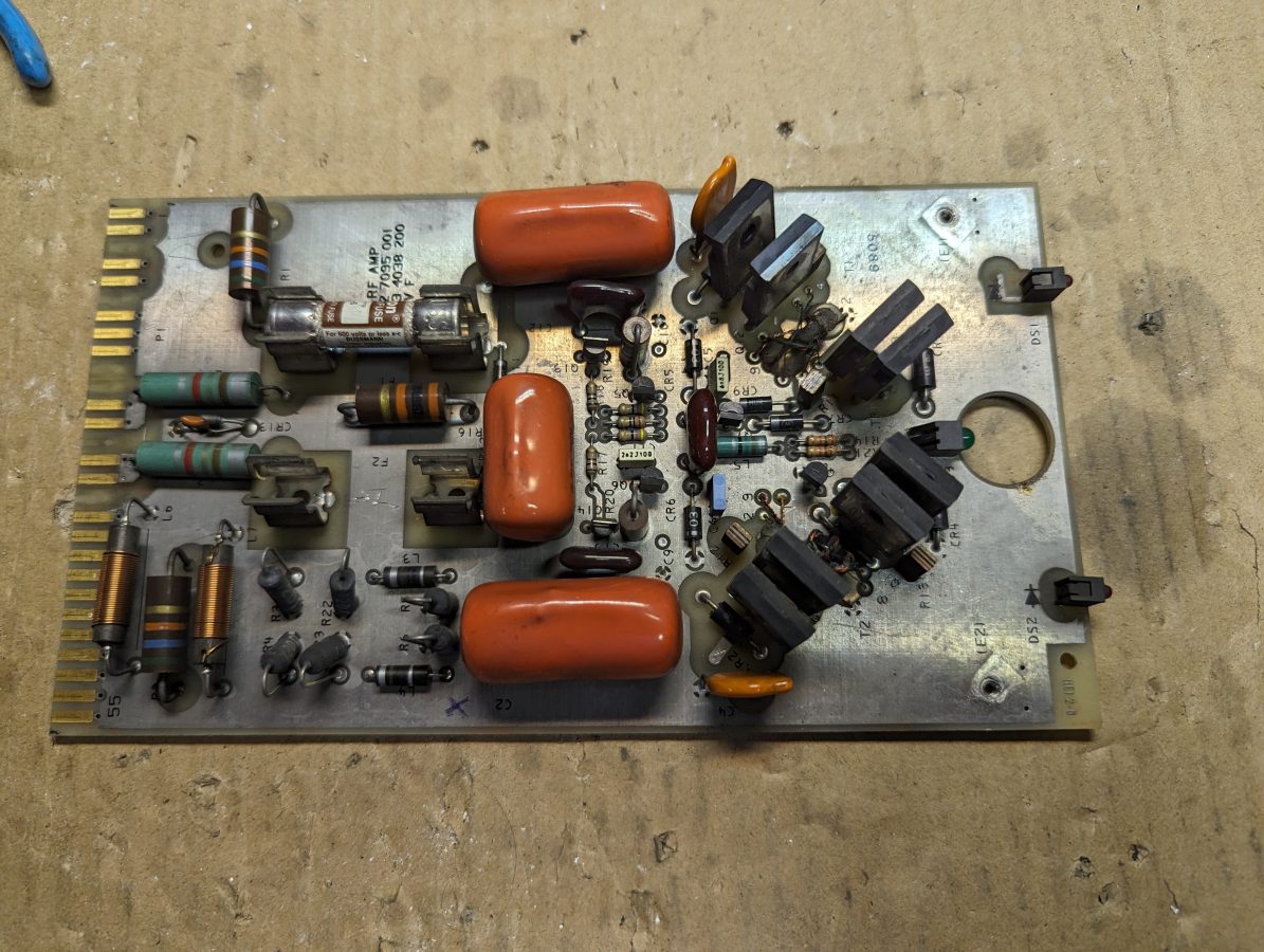
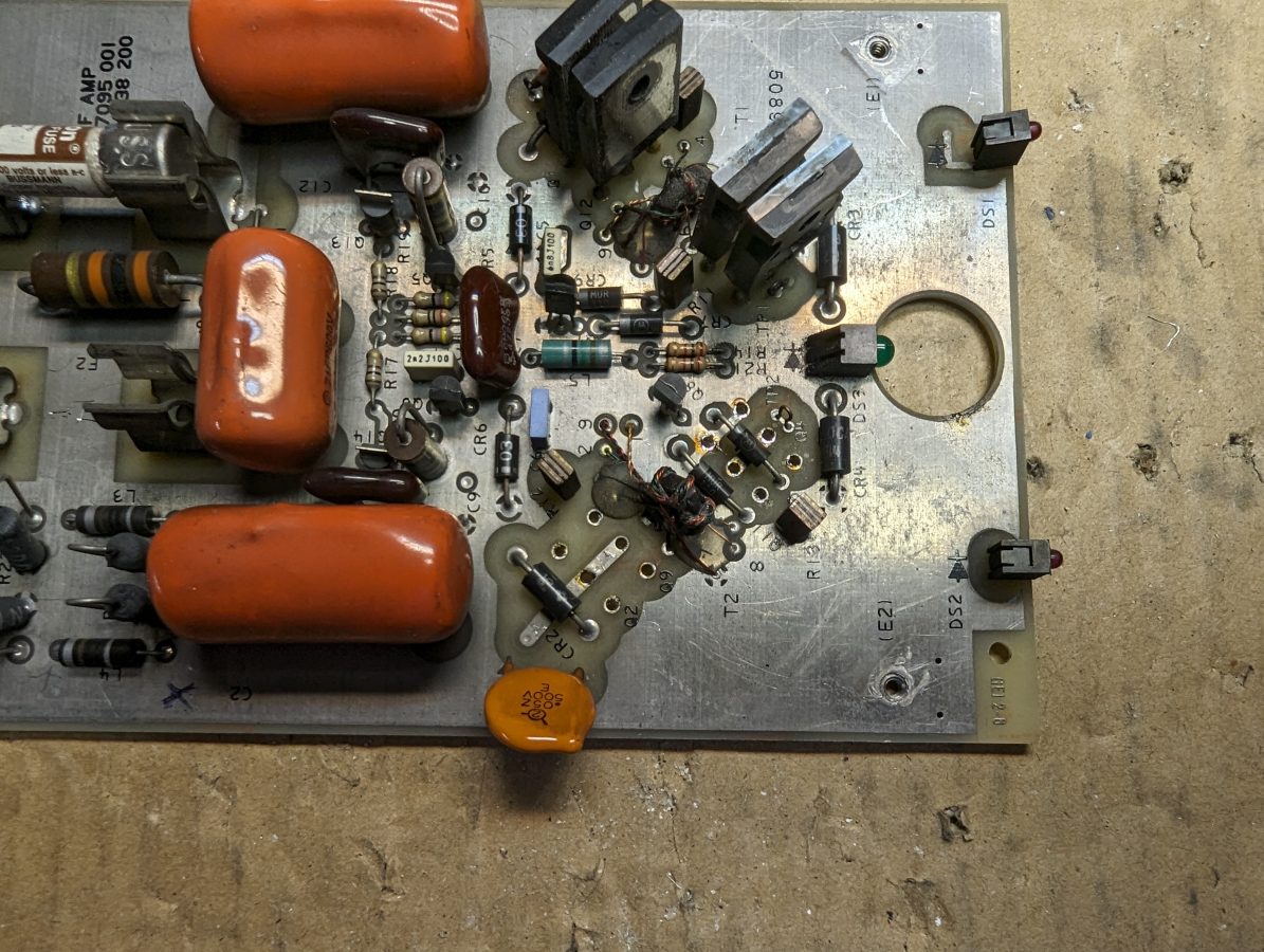
The first step is to remove the heat sink. I used a small screwdriver under the leads to gently pry the MOSFETS off of the heat pads. If you are careful, all of the heat pads will survive. Once the heat sink is off, I remove all four of the suspected MOSFETS. The leads are heavy gauge, so it takes a little bit of work with the solder pump and solder wick. I tested each MOSFET and found one shorted unit, the other three test okay. However, since these are inexpensive devices, I replaced all four.
Good device:
Bad device:
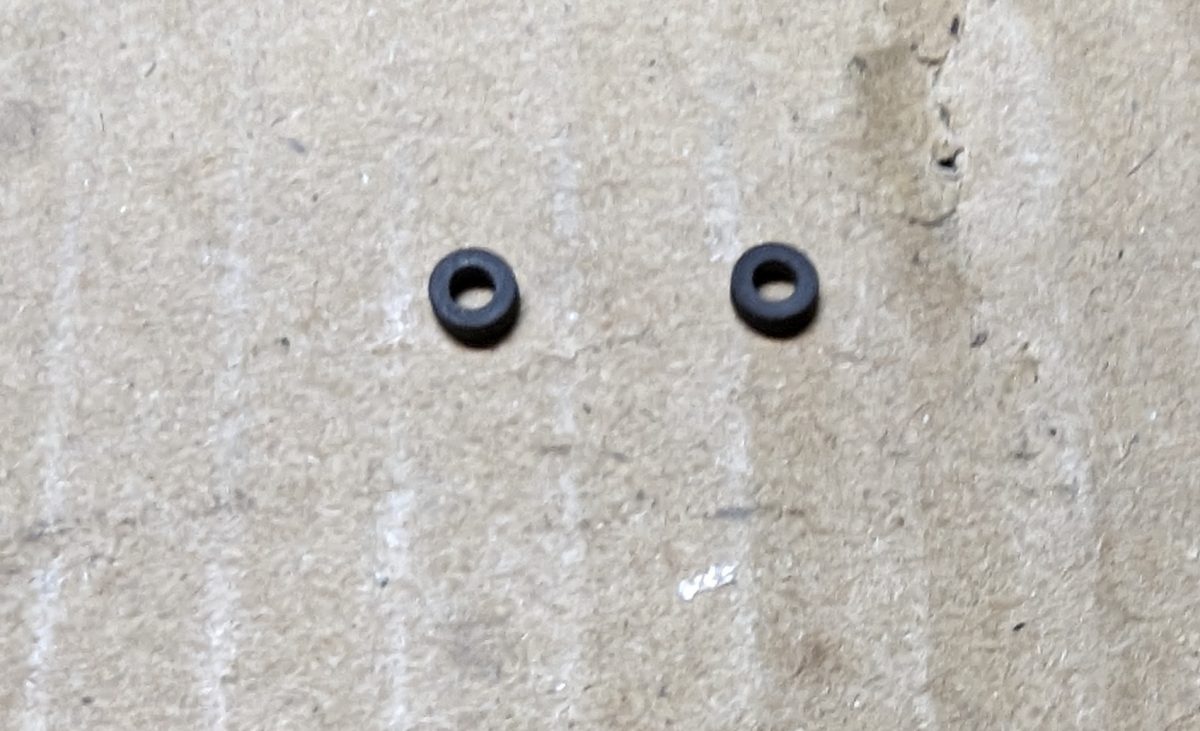
Assembly is in reverse order. Make sure that none of the insulating pads were torn during disassembly. I like to get everything attached to the heat sink before soldering the leads. It helps with lining everything up. Take care and make sure that the ferrite beads on the drain leads of Q3,10 and Q4,11 are re-installed with the new devices. These are necessary to prevent high-frequency oscillations.
Of course, the final test is in the transmitter. Generally speaking, I test the standby transmitter into the test load every two weeks. This is done in conjunction with the generator load test so as not to spin up the demand meter.