Tower lighting transformers, isolation chokes, etc

Series excited AM towers require some way to get standard AC across the base insulator to the tower lights if tower lights are required.  While many new AM towers do not have base insulators, through the use of a folded unipole, it is still a very popular design and has several technical advantages.

There are two methods for getting 60 Hz AC from zero RF potential to an excited tower:

  1. Tower lighting choke
  2. Austin Ring transformer
LBA Group TC-300 tower lighting choke
LBA Group TC-300 tower lighting choke courtesy LBA Group, Inc

When to use it depends on the tower and the RF potential on the base of the tower. For towers that are under 140 electrical degrees (RF) and carrier power levels up to 100 KW, a lighting choke works well. They are simple and less expensive than an isolation transformer.  They can be installed inside the ATU cabinet or placed in their own weatherproof enclosure as required.  Tower lighting chokes will add series impedance to the base of the tower and needs to be compensated for by adding capacitance to the circuit.  This will become more pronounced at the lower end of the band, where, if one is not careful, RF from the tower can be coupled to the transmitter building’s AC mains, which is very undesirable.

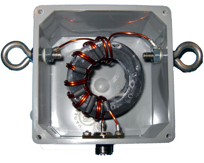
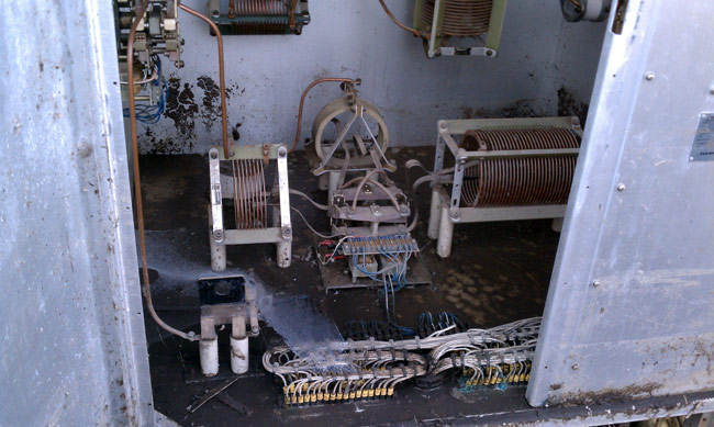
Tower lighting chokes generally consist of three separate windings, one for the beacon, one for the side lights, and one for neutral.  Their inductance is typically in the 800-1000 µH at 1 MHz region.  They can be stacked to increase their peak voltage handling capacity:

LBA Group tower strobe light choke
LBA Group tower strobe light choke courtesy LBA Group, Inc

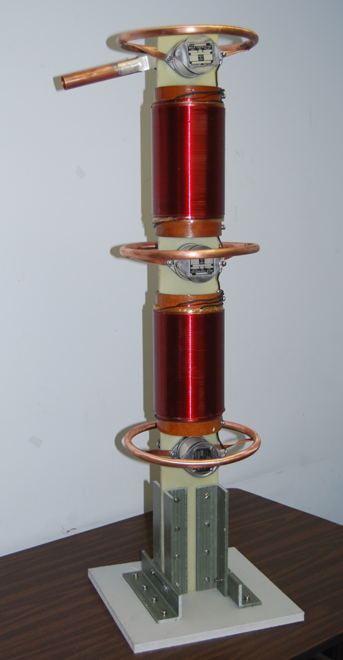
Peak voltage is determined by the base impedance and carrier power + modulation.  On any AM station these days, a 150% peak modulation figure should be used (125% modulation allowed by FCC rules plus a 25% safety factor).  For example, station B has a base impedance of 50Ω (typical 90° guyed tower) and a carrier power of 50 KW.  The peak modulation power will be 600 KW.  Thus, the peak voltage will be Epeak = √Ppeak x R, or Epeak = √600,000 watts x 50 ohms or 5,477 volts.   With higher base impedances, the base current goes down but the base voltage goes up.  A typical 140° tower will have a base impedance of 760Ω.  Thus the peak base voltage for a 50KW carrier power modulating at 150% will be 21,354 volts.  This is the worst case scenario, as few installations are designed that way and every tower impedance is different than the theoretical self impedances given.

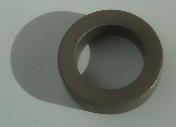
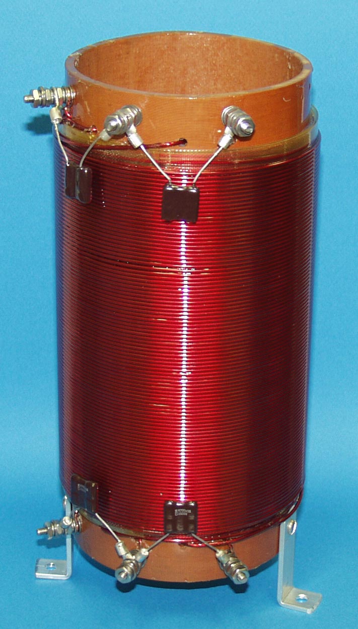
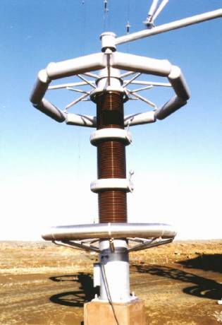
For towers over 140 electrical degrees, it is better to use an isolation transformer because of the RF peak voltage/peak current conditions at the base of towers that are electrically tall.  The ring transformer design minimizes stray inductance or capacitance at the base of such towers.  Austin Insulators (previously Austin Decca) makes a variety of tower base ring isolation transformers.  These have varying input and output voltages.

Diagram of typical Austin Ring transformer
Diagram of typical Austin Ring transformer courtesy Austin Insulators, Inc

I have seen these at many locations over the years. They are rugged and add only a small bit of capacitive reactance to the base of a typical tower.  They also completely isolate the building AC mains from the tower.  For very high-power installations, Austin has the A-9600, which was designed for the Navy VLF transmitter towers where base peak RF voltages can run 200,000 volts or more:

Austin A-9600 oil filled isolation transformer
Austin A-9600 oil-filled isolation transformer courtesy Austin Insulator, Inc

Voltage drop is another consideration in tower lighting design. Long runs from the transmitter building to the tower should be on heavy gauge wire and at 230 volts if possible.  FAA Circular AC 150/5345-43F “Specification for obstruction lighting equipment” advises that the input voltages for incandescent lighting systems vary by not more than ±3%.   Additional tower lighting and painting information can be found in FAA Circular AC 70-7460-1K.

What is “Phasing” as it relates to radio?

Occasional reader Jeffery asks a good question, which I will attempt to answer here in simple terms. Phasing, when used with antennas, refers to the relationship that two or more radiating elements share with the waveform being transmitted.  It is used to create an RF radiation pattern by adding energy to the wavefront in one direction by taking energy away from the wavefront in another direction.

Phasing is often described as +/- X number of degrees from a reference point.  Graphically, it would look like this:

One wavelength with +/- 180 degrees notated

The reference point can be changed to any point on the waveform, in radio applications it is usually oriented around +/- 180 degrees.  If the reference point is a single tower or element then this would be the end of the story. Add a second tower to this system and it would look something like this:

Double wave form
Double waveform

In this picture we have two waves being radiated from two separate elements. These elements are spaced 100 degrees apart and tower #2 is phased to +90 degrees.  RF generator is coupled to both towers via a power divider, the reference tower (tower #1) is feed with 57% of the power that tower #2 is being feed.  Thus, the ratio of power to the respective towers would be 57:42.  Thus, if tower one had a power reading of 1.00, tower two would be 0.74.  The towers are on a north/south line with the reference tower bearing 180° from tower #2.  In the area of subtraction, the waveforms from each tower cancel each other out to some radiating less power toward the south; in the area of addition, the waveforms sum to create a more powerful waveform, radiating more power towards the north.

Resulting pattern (WKIP, Poughkeepsie, NY):

WKIP 1450 Poughkeepsie, NY pattern plot

This is a typical two tower array, however, there are two slight differences; the reference tower is 215 degrees tall, tower two is 90 degrees tall. This is yet another use of “degrees” to relate electrical length or separations. The second, more notable distinction is that this array is Directional daytime, and non-directional night time, which is the opposite of most AM stations in this country.

Electrical height can also be described as a function of wave length, e.g. 1/4 wave, 1/2 wave, etc.  Most AM towers in this country are 1/4 wave length, which equates to 90 degrees.  Often, higher powered stations, and some low powered stations put up towers near 1/2 wavelength due to the better ground wave performance of those towers.  At lower dial positions, a 1/2 wave tower becomes an expensive proposition due to the height required.

In theory, an unlimited number of towers can be used to create a pattern by introducing nulls (areas of subtraction) and lobes (areas of addition).  In practice, the highest number of towers I’ve ever heard being used in an AM directional array is twelve; KFXR 1190, Dallas, TX.  There may be others, too.

An excellent resource for AM directional antenna technical information is Jack Layton’s Directional Antennas Made Simple, which is out of print but available from various sources.

Emergency AM replacement antenna

Eventually, disaster will strike. It can range from a fire at the transmitter site to a tornado at the studio.  Someday, every station on the air will be knocked off at the worst possible moment. It is the law of nature.  Perhaps the most difficult disaster to recover from is the loss of a tower at a transmitter site.  An FM tower holds the antenna, therefore, finding a tower or building nearby and placing a temporary antenna there will get the station back on the air in a reasonable fashion.

An AM tower is the antenna, which is much harder to replicate.  One possible solution is to use a temporary wire antenna while the tower is being rebuilt.  This is allowed in FCC 73.1680 emergency antennas, provided the commission is notified of the situation by informal letter.  Directional stations must operate at 25% or less of the station’s licensed power, or demonstrate that radiation limits are not being exceeded in any direction.  That usually can be accomplished by taking a set of monitor points.

A wire antenna can come in several configurations:

  1. The fastest to deploy is the random-length end-fed wire.  This can normally be attached to the existing ATU and tuned up with components on hand.  It requires having an OIB, generator, and receiver to tune, which not every station has.  In addition to that, extra components may be needed in the ATU for tuning purposes.
  2. The next easiest is a tower-length wire ready to deploy.  This is a length of wire equal to the height of the tower, with insulators and supports.  The wire should be supported as high above ground as possible using trees, wooden poles, etc.  Still requires having an OIB, generator, and receiver to tune.  Likely to be within the tuning limits of the ATU components on hand.
  3. A 1/2 wave dipole tuned for 50 ohms.  This can be connected directly to the transmitter output, thus is the best solution if the ATUs were damaged or otherwise not serviceable.  In this situation, two 1/4 wavelengths of wire are coupled at the center using a 1:1 balun.  Again, this antenna should be supported as high above ground as possible using trees, poles, and other non-conductive supports.  Can be installed in a V, inverted V, or L shape as required.

All three of these choices would likely limit transmitter power output to 1-2 KW.  Choice 3 likely represents the most efficient radiator and can be fabricated ahead of time and stored at the transmitter site.

1/2 wave dipole with 1:1 balun

To make a 1/2 wave dipole, cut two lengths of wire using the formula L(feet)=246/F(MHz).  This formula does not account for a velocity factor of 90%, which is typical for stranded wire.  The reason is, since an MF dipole antenna is necessarily going to be lower than 1/2 wavelength, it is better to start the antenna a little long and trim it to size for a 50-ohm impedance.  If commercially made insulators are not available, insulators can be made from non-conductive materials like PVC conduit, PEX, plexiglass, etc.  The insulators on the ends of the wire need to account for the voltage peak that will occur there.  If small “dogbone” type porcelain insulators are used, string three or four of them together using nylon or poly rope.  The insulator needs to be able to withstand 8-10 KW of power under full modulation.

A 1:1 balun will distribute the RF currents evenly on both wires, which will help improve efficiency and coverage.  Most Ham Radio Baluns are not designed to work below 1.8 MHz and therefore, will not work for this purpose.  A balun can be made with a ferrite toroid made from 68, 73, 77, or type F material.  A good choice would be Amidon FT-290-77 or FT-290-F.  The type F material has a higher AL value, thus fewer turns are needed.  In addition to that, high voltage insulated wire should be used to wind the balun.

1/2 wave dipole antenna current voltage distribution

Since, in a 1/2 wave dipole configuration, the voltage is at a minimum at the center of the antenna, and current is at a maximum, some attention needs to be paid to wire size as well.

Amidon ferrite torroid core

To give a good idea of wire sizes required, some basic information is needed.  For a 1 KW station, it is assumed that the carrier will be modulated to 100 percent, therefore the peak envelope power will be 4 KW.  If the station is asymmetrically modulated, add another kilowatt.  Therefore, the maximum current formula is I=√(P/R).  P is the power in watts, or 5,000 and R is the radiation resistance or 50 ohms, thus I=√(5000/50) or 10 amps.   The maximum voltage is E=√(P x R) or E=√ (5000 x 50) or 500 volts.  For a safety factor, multiplying these values by 1.5 is recommended.  That will likely account for any impedance differences due to ground proximity and so forth.  Therefore for a 1 KW station, the dipole antenna should be designed for 15 amps and 750 volts.

For a 2 KW station the peak envelope power for an asymmetrically modulated transmitter is 10 KW, thus it follows that 30 amps and 1500 volts are safe working figures.

With the proper torroid core, a turns count of 7-10 turns bifilar will suffice.  Since it is a 1:1 balun, the turns count on both sides of the transformer will be the same.  The balun then should be placed in a suitable water proof housing designed to be attached to the center of the dipole antenna.  This is a good example of a commercially available 5 KW 1:1 balun for amateur radio use:

1:1 balun designed for center of 1/2 wave dipole antenna

The antenna can be fed with RG-8, RG-8X, RG-8A, RG-214 or any other coax this is capable of handling the peak envelope power of the radio station.  The connector can be UHF, N, LC, etc.  In some cases, the may be easier to simply omit the connector and connect the coax to the balun using some type of strain relief on the cable coming out of the box.

Once this antenna is made, a bit of tuning may be required to bring it to 50 ohms.  This can be done with a bridge and generator, or with the transmitter on low power.  Either way, the measurements must be taken with the antenna at operating height as the distance to ground will effect the termination point impedance.  It may require some trial and error.

In all, a good backup antenna can be made for about $50-60 or so.  A little bit more if fancy transmission line is used.  Well worth the expense and effort to have something ready to go in a moment’s notice.

Update: I’ve been fooling around with this on EZNEC, it may not be that easy to do, especially with the lower frequencies in the AM band.  The antenna needs to be at least 0.06 wave length above ground to perform correctly.  Somewhat lower over better ground conductivity, e.g. ground radials.  Even at this height, it needs to be lengthened significantly to get the feed point impedance close to 50 ohms.

Creek floods AM tower array

We have received somewhere between 5-6 inches of rain in the last four days. That, coupled with the deep snowpack and the still-frozen ground has led to some flooding. The WLNA antenna array is located along the Peekskill Hollow Creek in northern Westchester County, NY.  Back in 1980, it might have seemed like a good idea to locate an AM station in a tidal swamp along the Hudson River.  I am sure the land was not that expensive and from an engineering standpoint, having a continually wet, partially brackish ground system may have seemed like a slam dunk.

Unfortunately, the idea never really panned out in the application.  First of all, the neighbors had other ideas, fighting the radio station owners all the way to the NY State Supreme Court.  Secondly, technically, it never lived up to expectations.  The original non-directional antenna on 1430 was a 1/2 wave tower which by all accounts, worked very well.  It did not, however, allow for nighttime service, which is why the new sight and array were sought.  By the time the system was built, AM was already in steep decline and I doubt the owners ever recouped their investment.

Fast forward to today.  All five base insulators are under water and the transmitter is off the air.  These are pictures from last Wednesday after the first flood waters receded from the Monday/Tuesday storm.  I imagine it looks worse this morning, although I don’t own a boat and won’t be wading out there to look.

Base insulator, tower 2 WLNA array, Peekskill, NY

This is tower two of the daytime antenna array.  Clearly, it spent some time underwater.  We cleaned off all the debris from all the tower bases.  A far worse prospect is the ATU’s:

WLNA tower 1 ATU, Peekskill, NY

This is the Antenna Tuning Unit for tower 1, which is the reference tower for both the day and night arrays.  The E.F. Johnson contactor in the bottom of the cabinet was fully submerged for an undetermined amount of time.  The bottom of the unit is covered in fine silt.  The high water mark is visible on the right side of the aluminum cabinet.

The contactor is going to need to be replaced, or at least rebuilt.  The ATU cabinet will need to be washed out.  There are two other ATUs that suffered the same fate.

WLNA antenna array, towers 4 and 5
WLNA antenna array, towers 3 and 5

This is the end of the catwalk next to the Peekskill Hollow Creek looking west towards the Hudson River.  The water level reached the bottom of the catwalks and had receded about 4 feet when this picture was taken.

WLNA antenna array, tower 5, peekskill, ny
WLNA antenna array, tower 5, Peekskill, NY

Lookup east, upstream at tower 5.

WLNA antenna array looking north, Peekskill, NY

This is the antenna array looking north, with my back facing the creek.  Tower one is the center tower, tower two is on the right and tower four is on the left.  The daytime array consists of towers 1, 2, and 3 bearing 300 degrees.  The night time array consists of towers 1, 4, and 5 bearing 335 degrees, so the array makes a big X in the swamp.  More from the FCC database.

It is going to take a lot of work to clean out all these ATUs and repair the damage.  Clean water is at least 1000 feet away.  My question is; why bother?  Once upon a time, this station was viable, well thought of in the community, etc.  Now, I doubt anyone knows it is off the air.  The current ownership over the last thirteen years did, what I’d like to call, a controlled flight into the ground.  Axing staff, cutting maintenance, and generally neglecting the station.  Why not take it dark for a while and figure out what to do with it?  Likely somebody would buy it, even if for the land it sits on.  Anyway, the grind continues…