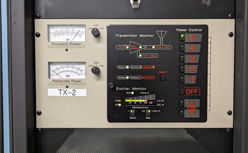
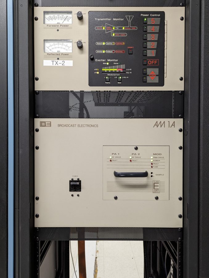
This particular power supply is used in Broadcast Electronics AM1A, AM2.5E, AM5E, AM6A, AM10A, FM1C, FM10T, FM20T, FM30T and FM35T transmitters. It is a Computer Products NFN 40-7610, 40 Watt, +5 VDC, +/- 15 VDC BE part number 540-0006.
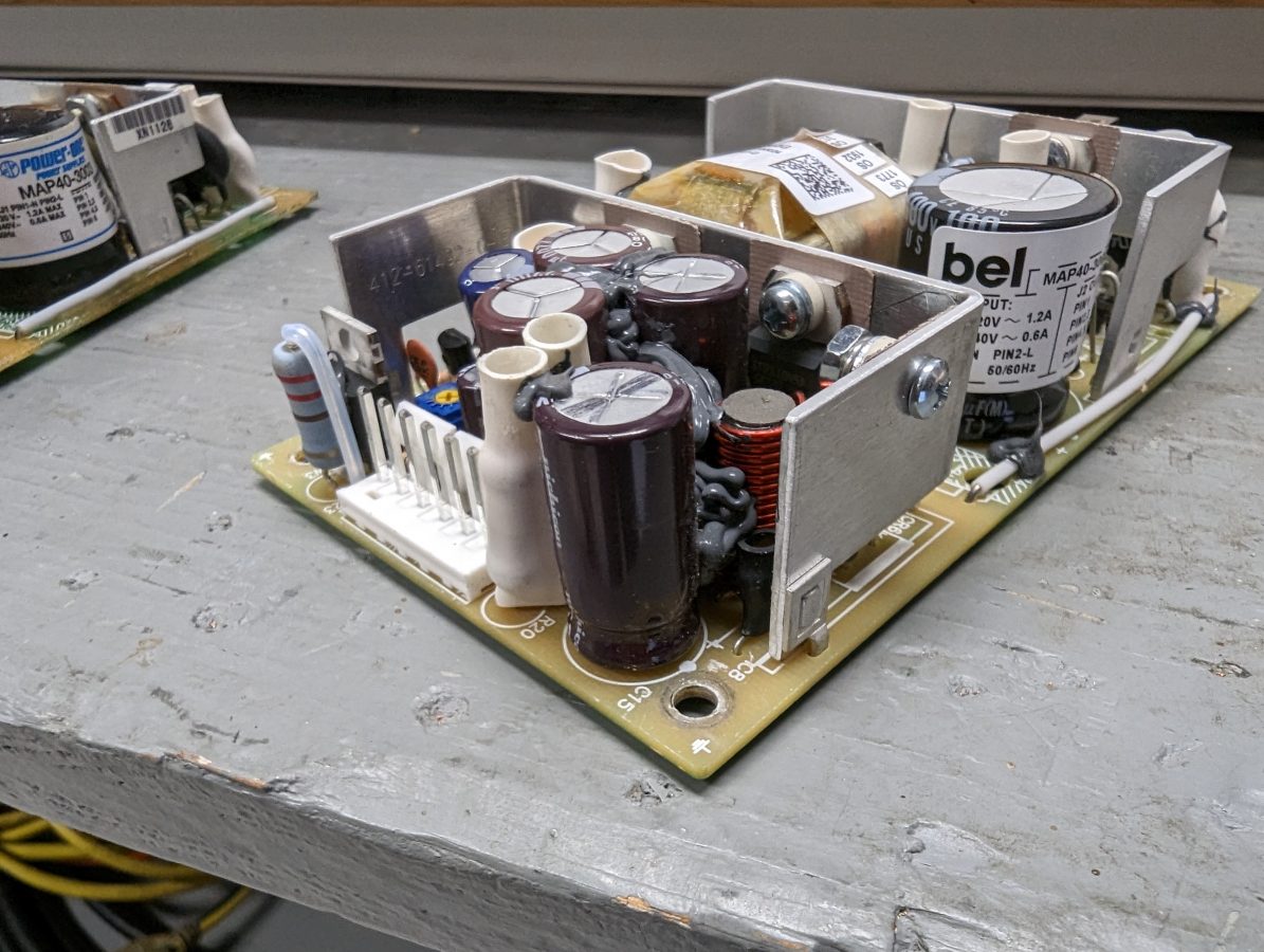
BE AM1A ECU power supply, C-15 marked with pen for replacement
Generally, one component fails over time on this unit, C-15 which is a 680 uF 35 V electrolytic capacitor. When that capacitor dries out, the power supply will fail to start, do odd things like start and fail after a second or two, or cycle on and off. This will happen after the transmitter has been off for a few minutes. Replacing C-15 with a 1000 uF 50 V capacitor will fix the problem. There is enough room for the larger capacitor if the leads are left a little bit long.
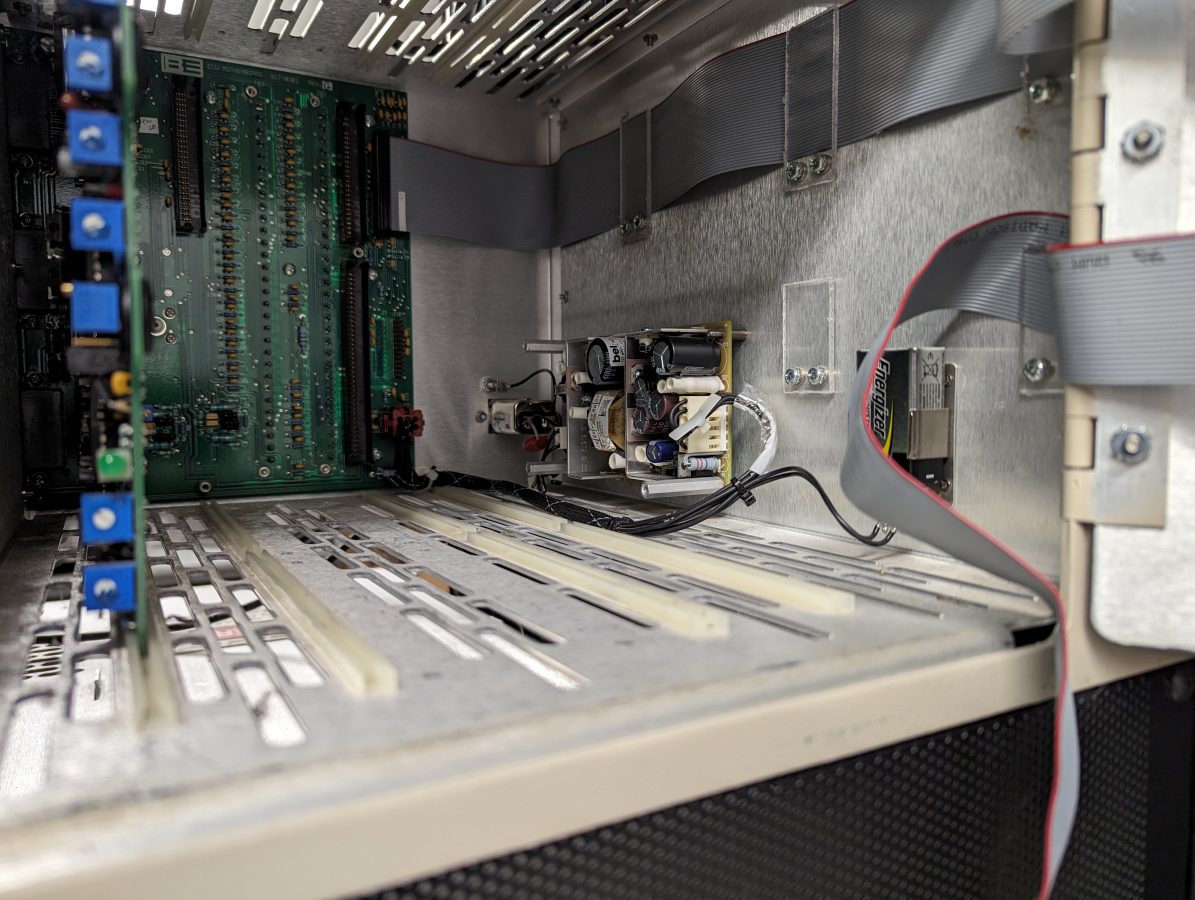
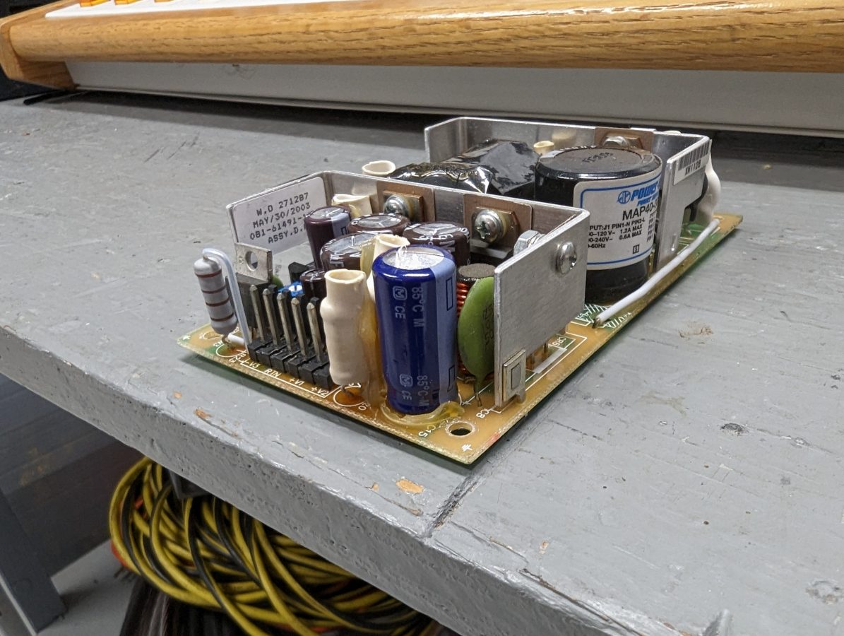
BE AM1A repaired ECU power supply re-installed
We have several of these repaired units on various shelves at various transmitter sites.
As always, when replacing electrolytic capacitors, pay attention to the polarity otherwise this will happen:
Blown Electrolytic Capacitor installed backward
I suppose somebody was in a hurry to get home that day. After I installed this repaired unit, it ran for about 15 seconds and then there was a pop. I opened the door on the ECU and white smoke was wafting out from under the power supply cover. Since the Pope is still The Pope, I knew it was the electrolytic capacitor.
Back in business
Our beloved BE AM1A is back in service. This transmitter is 22 years old and we can keep it going for as long as parts are available.
I want to explore all digital modulation methods for Standard Broadcast (AM, Medium Wave, or Medium Frequency). The most pressing technical problem for AM reception is electrical impulse noise. Can digital modulation solve this problem? Perhaps, but I am a natural-born skeptic.
To start out; I will say up front that the hybrid HD Radio (MA1) employed on AM was (or still is) a travesty. It never worked very well and it created massive interference +/- 20 KHz of the assigned frequency, especially when employed at night. Secondly; the all-digital version of HD Radio (HDMA3) remains a proprietary system with non-standard codecs. The current owner, Experi, has a license fee structure based on station type (AM, FM, LPFM, or Non-commercial) which ranges from $5,000 to $10,000 one-time fee for a five-year period. In all fairness; DRM pays a technology license fee to Fraunhofer for MPEG codecs used by receiver manufacturers and broadcast equipment. This is estimated to be between $0.13 to $1.13 US per receiver.
Those things being said, I thought a deep dive into the technical side of HDMA3 and DRM (Digital Radio Mondial) would be interesting. I did an article comparing MA3 and DRM a while ago: All Digital Medium Wave Transmission
What challenges are there to transmitting digital radio on MW? First, there is the very limited bandwidth of the channel itself. In North and South America, AM channels are spaced every 10 KHz (9 kHz in other places). On Medium Wave, the analog channel is +/- the carrier spacing, e.g. 20 KHz (or 18 KHz) with half of that channel potentially interfering with the adjacent channels. On a 20 kHz channel, this limits data transmission rates to 72 kbps or less with DRM and 40 kbps or less with HDMA3.
Secondly, skywave propagation is a potential difficulty for all digital broadcasts. Ionospheric changes can create multipath and fading, especially as the sun rises and sets causing the D layer to form or dissipate. Changes in the E and F layers can make or completely break skywave reception. Ground wave reception is reliable out to the limits of the noise floor, and varies based on transmitter frequency, power, and ground conductivity, and electrical noise in the area.
Everything that can potentially mitigate noise and skywave reception problems is a trade-off between robustness and data throughput.
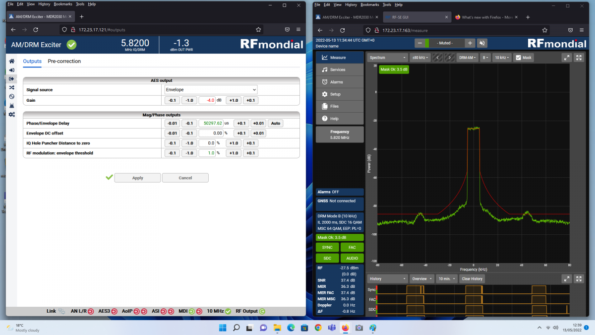
Screenshot of an HF DRM exciter from RF Mondial showing a 10 KHz wide channel on HF.
Screen Shot of an HF DRM transmission showing mask, courtesy of DRM Consortium
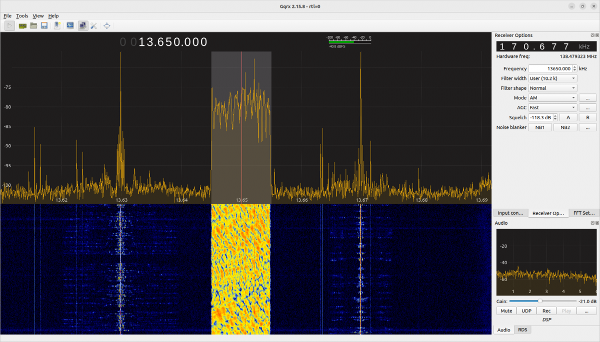
This is a screenshot of an SDR showing an HF DRM transmission received from a distance:
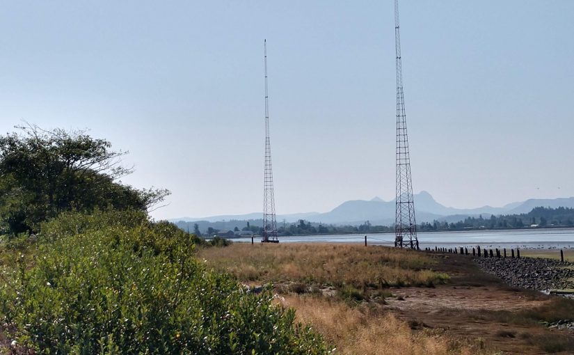
Radio Romania International, 13,650 kHz 90 KW, 7,530 KM path
The receiver is not quite on bearing for this broadcast, however, it seems to be doing well. This is Radio Romania International’s Spanish broadcast targeting South America. The Pan Adaptor shows the signal is 10.2 kHz wide, but that doesn’t mean much from a $30.00 RTL SRD. The waterfall display below shows it is spectrally dense compared to the analog signals to the left and right. Note that with DRM there is no analog carrier being sent. Instead, a series of pilot tones are attached to various OFDM subcarriers for the receiver to lock onto.
A short Primer on COFDM
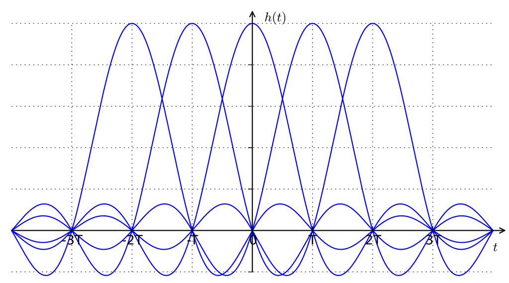
The modulation method for both systems is Coded Orthogonal Frequency Division Multiplexing (COFDM), which is the same system used by mobile phones, cable systems, WiFi (802.11), ATSC 3.0 TV, etc. COFDM consists of a group of subcarriers multiplexed onto one channel. The number of subcarriers and the subcarrier spacing relates directly to the data throughput and the robustness of the signal. OFDM is a very robust method that works well in the upper VHF, UHF, and SHF bands. It can work well in lower frequencies, however, there can be issues with multipath and Doppler effect. The coded part consists of forward error correction, which may include interleaving and subtracts from the data throughput.
The ability of an OFDM signal to reject electrical impulse noise, and deal with potential fading or multipath interference is based on a few things. The cyclic prefix sets the Guard Interval for the OFDM frame. The length of the Guard Interval should be the same as the multipath delay which helps mitigate inter-symbol interference and inter-subcarrier interference. Since the Medium Wave channels are fairly narrow, the number of OFDM carriers and spacing between carriers have a great effect on robustness. The fewer carriers the more robust the signal. This comes at the expense of data throughput; the fewer carriers the less data can be sent.
Raised Cosine impulses, similar to Orthogonal frequency-division multiplexing. (2023, May 10). In Wikipedia. https://en.wikipedia.org/wiki/Orthogonal_frequency-division_multiplexing
A short Primer on QAM
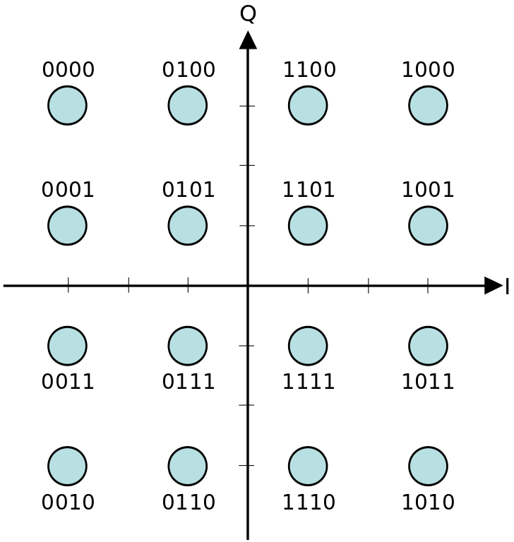
Each individual OFDM subcarrier is modulated with a Quadrature amplitude modulation (QAM) signal. The advantage of this is that each individual carrier sends data at a relatively slow rate and the aggregate data rate is the sum of all the subcarriers. QAM uses two carriers 90 degrees out of phase. The amplitude of each carrier determines the resultant vector of the modulated wave to create a data bit. For example; the sum of the carriers equals +45 degrees at 25% amplitude a 1101 data bit is sent.
16-QAM Constellation diagram. (2022, December 17). In Wikipedia. https://en.wikipedia.org/wiki/Constellation_diagram
Both HDMA3 and DRM can use 16-QAM or 64-QAM. The larger the QAM constellation the more data can be sent. Smaller QAM constellations are more robust. HDMA3 can also transmit QPSK, which is Quadrature Phase Shift Keying. The resultant waveform from QPSK is identical to 4-QAM.
Bringing it all together
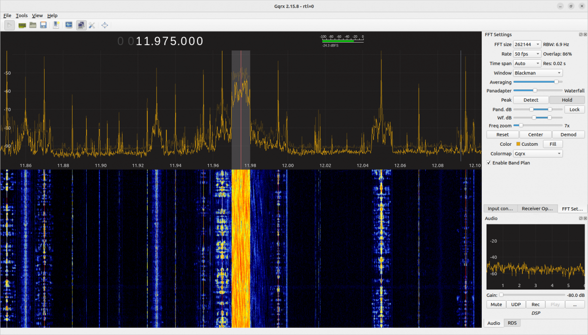
Radio Romania International, 11,975 KHz 90 KW 7,530 KM path, English service to Western Europe and North America,
A DRM-modulated HF and MF transmitter uses both sidebands to transmit unique information. There is no carrier present but rather a few pilot frequencies for the receiver to lock onto.
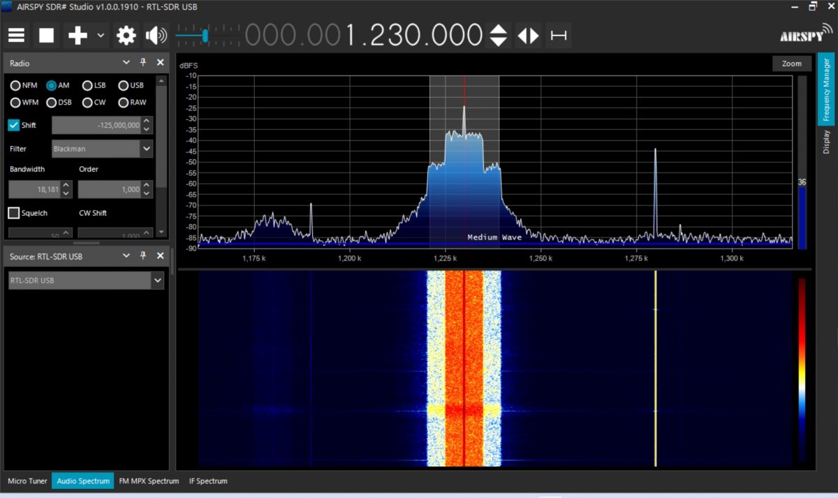
WFAS White Plains, NY All digital HDMA-3 signal
I like the waterfall display available with many SDR software programs. It gives a good indication of modulation density. With WFAS HDMA-3, the area +/- 5 KHz of the carrier signal has more power than the areas that are +/- 5 to 10 KHz from the carrier.
An HDMA3-modulated MW carrier sends the same data on upper and lower sidebands, effectively halving the data rate of DRM. There is a full carrier present, which represents approximately 25% of the transmitted power and does not contain any data. Currently, there are four three HDMA-3 stations transmitting in the US.
Both systems can make pre-corrections to the modulated signal in the exciter to compensate for amplifier non-linearities. This can greatly improve the MER and SNR.
The other perceived technical issue with AM radio is sound quality. This has to do mostly with poor-quality receivers, although there are some AM stations that are transmitting reduced-quality audio as well. There is a false notion that anything “digital” sounds better than analog. I would posit; it depends on several factors. Low-bit-rate audio codecs can sound abysmal. That being said, the newer high-efficiency audio codecs can sound quite good, but there are limits. With HD Radio, there is only one codec available; HDC+SBR. With DRM there are several; xHE-AAC, HE-AAC. xHE-AAC is designed to work with voice and can use bit rates as low as 12 kbps. It is possible for a robustly transmitted low-bit-rate codec to sound good with voice. It can sound okay with music, but not as good as analog FM.
Conclusion
Can an all-digital modulation format work well on the Standard Broadcast Band? The answer is; it’s complicated. One of the big positives of AM is that it is a very simple and well-tested system. Adding many layers of encoding and decoding is a violation of the KISS principle. That being said, using a digital modulation method that has been refined for mobile use over the years is a step in the right direction. There still is an issue with digital receivers; both HD and DRM. From what I have read, both formats are currently being included in several radio chip sets, yet I do not find those options in most car radios. There is a lack of public awareness, at least in the United States about digital radio in general. When someone says digital, most people think of streaming. When I am driving a rental car, I seldom find HD Radio, I do find Sirius/XM and all types of internet connectivity via smartphone apps.
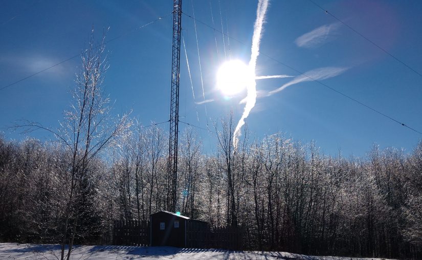
Call it climate change or an unfortunate coincidence; we seem to be getting more icy weather in this area. It used to be this region would see one mild event every one or two years. Recently, however, we are getting two to three moderate to severe events per year.
This can create problems for the utility company. Even if the power stays on, the transmitter may not. Excessive ice on the antenna may cause the transmitter to fold back or shut down completely.
We have several clients that have various FM antennas with electric resistance type de-icers. One client has three such stations however I found there were no automatic controllers at any of them. Back in the day, when there were people working at the station, they probably turned the de-icers on and off manually via the remote control. These days, not so much. When we began servicing these facilities, the previous engineer stated that he turned the de-icer breaker on around Thanksgiving and turned it off around Easter. Not terribly efficient.
As a part of moving into a new transmitter building, I began looking for something that would automatically turn the de-icer on when it is precipitating at or close to freezing temperatures and then turn it off after a couple of hours. That would certainly reduce the electric usage for that transmitter site and keep the transmitter happy.
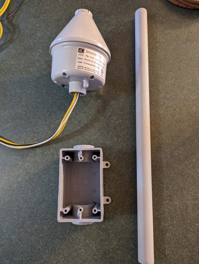
I found this simple snow melt controller:
ETI LCD-8 snow melt controller
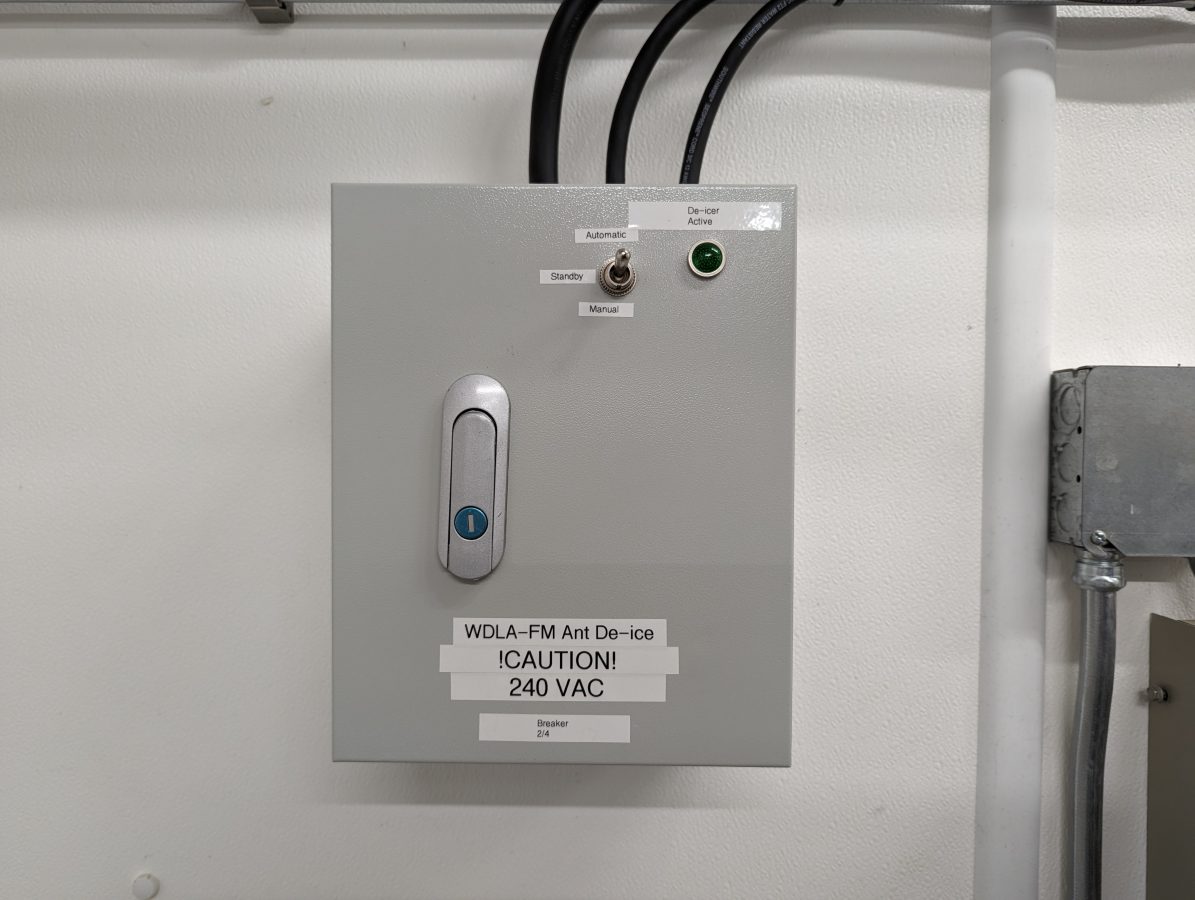
This is sold on Amazon for about $570.00. This has an internal relay that can switch 240 volts at 16 amps. However, that 240-volt heating circuit goes up to the top of the tower where the FM antenna is mounted making it vulnerable to lightning damage. I figured an outboard relay switched on and off by this controller was a better way to go. That way, there is an operating indicating lamp and a bypass switch.
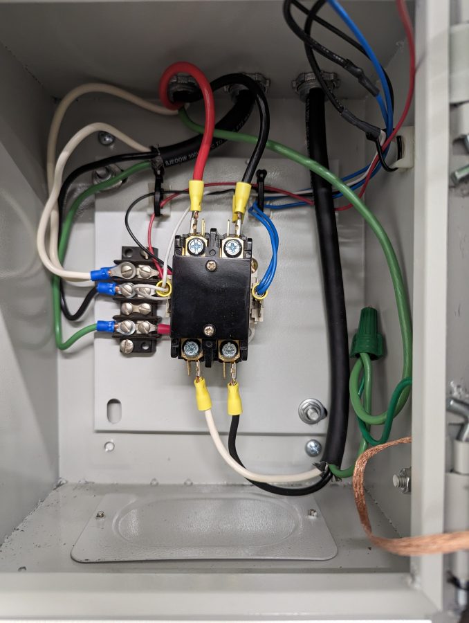
De-icer controller relay
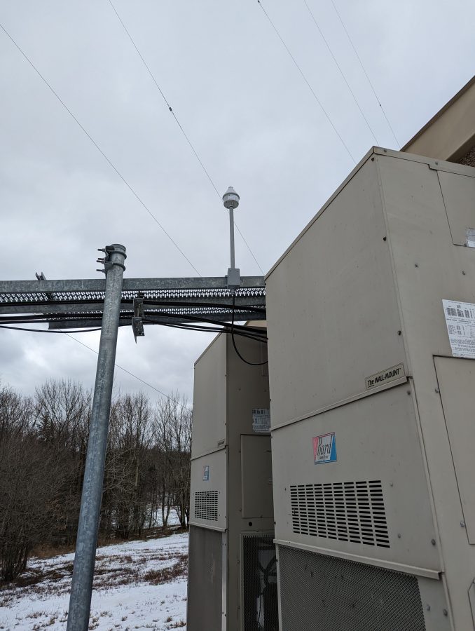
Outdoor icing sensor mounted on the ice bridge.
Now, the de-icer stays off most of the time. When it is needed, it comes on automatically and turns off three hours after the precipitation has stopped. Since installing last fall, it has worked well and the station stayed at full power through at least two ice events.
I measured the current on each leg, which was 2.6 amps or 624 watts. That is the same as it was before. A quick calculation, I estimate the number of hours this system was previously energized when the breaker was left on all winter to be roughly 3,400. Thus 3,400 hours x 624 watts = 2112 kWh. These days, our electric rates are running $0.16 to $0.18 per kWh so the total cost would be $380.00 to run continuously. The control system will pay for itself in less than two years.
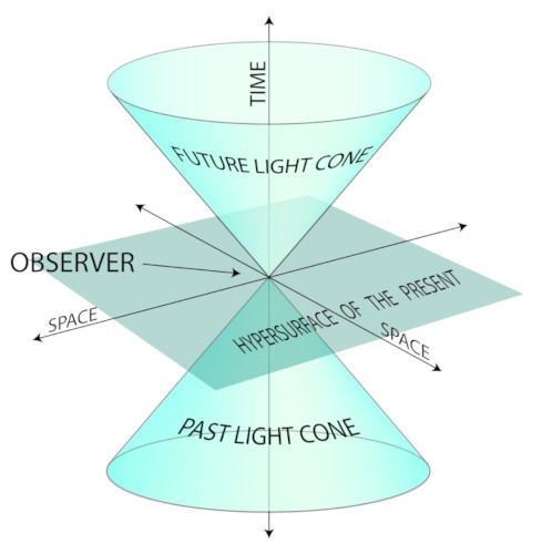
This is an important question these days. We are running into more situations where timing is important, especially when audio and video codecs are concerned. If there is too much time differential, the codec will unlock. More often, digital transmission methods require precise timing to prevent jitter and dropouts. Some equipment has 10 MHz or 1PPS inputs. Some equipment does not and relies on NTP to keep things in sync.
While searching online for GPS time sever, I came across this post where Austin built a Stratum 1 level time sever with a Raspberry pi and an inexpensive GPS receiver. I thought to myself; damn that sounds interesting. While a Raspberry pi is a hobbyist toy, the same setup can be done with a more serious computer to create a solid NTP server for a facility or LAN.
A little about NTP time servers; Stratum 0 server is directly connected to an atomic clock. Since GPS satellites have atomic clocks, that makes them a Stratum 0 server. Stratum 1 servers are connected to Stratum 0 servers. Stratum 2 servers are connected to Stratum 1 servers and so on. The time accuracy for a Stratum 1 server is 10 microseconds.
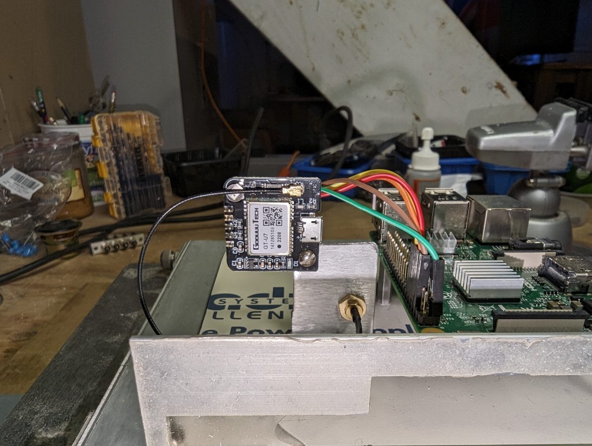
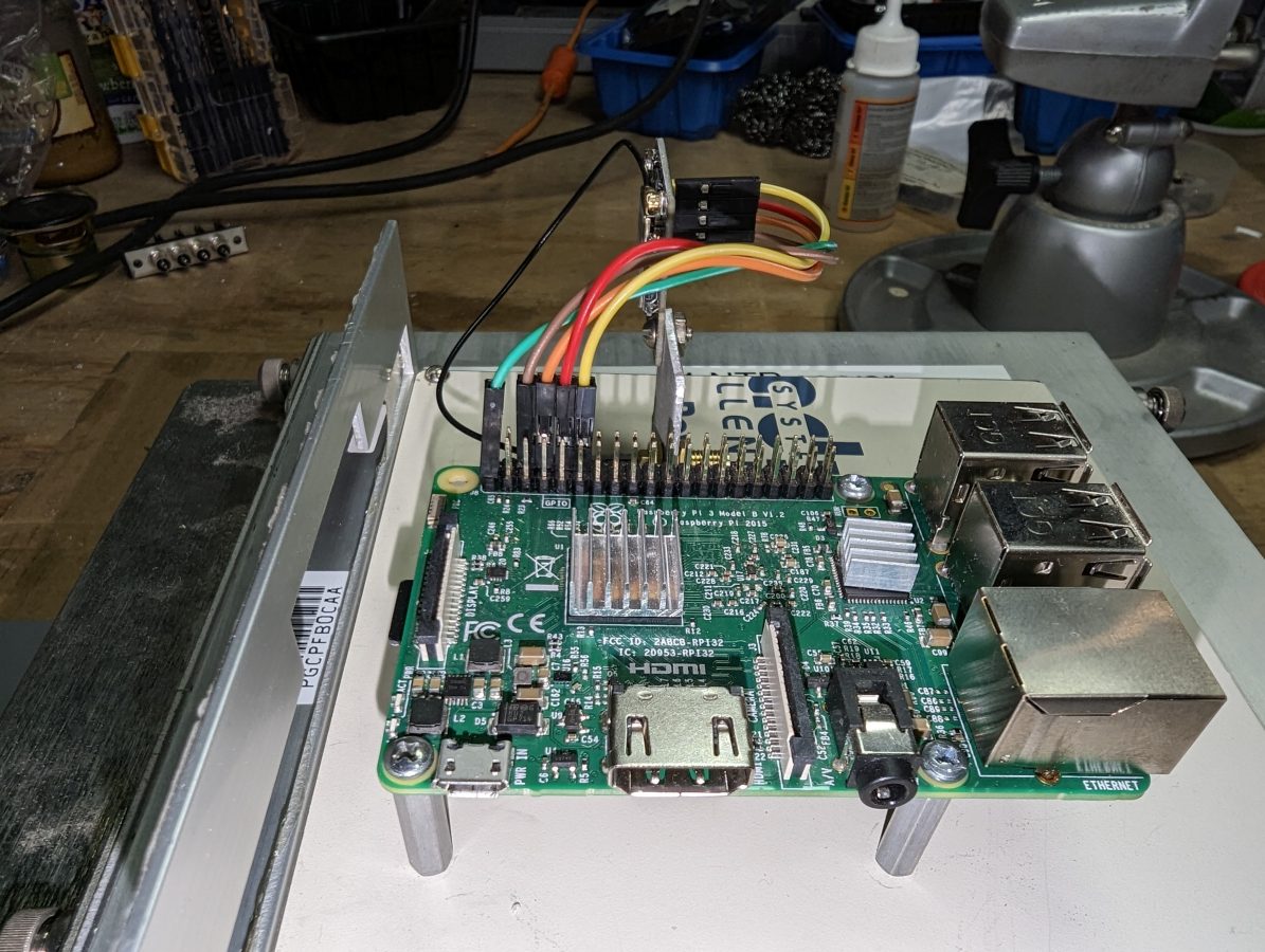
First, I wiped my SD card and loaded a fresh install of Raspberry pi OS. Then followed along with the instructions. For this install, I opted for the cheaper GPS receiver, the GT-U7 (not an affiliate link) from Amazon for $10.99. It comes with a cheap little antenna, which actually worked sitting inside on my desktop while I was configuring the software.
This little module is designed for a drone but works well in this application. The 1PPS output looks clean on the scope. Here is the pinout between the GT-U7 and the Raspberry pi:
GT-U7 pin
pi pin
Use
Color
vcc
1
+3.3 vdc
Green
gnd
6
ground
Brown
txd
8
rxd
Orange
rxd
10
txd
Red
pps
12
GPIO 18
Yellow
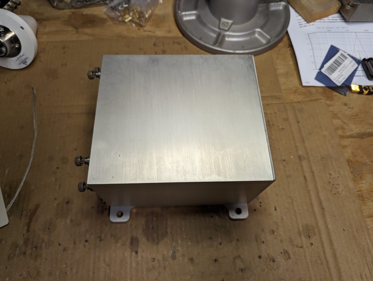
I found this really nice aluminum case in a pile of disused junk at a transmitter site. It used to be for a digital TELCO STL circuit. I figured it would be nice to put the Raspberry pi and GPS receiver in a suitable home.
Raspberry pi 3 is mounted on a piece of scrap sheet steel designed to slide into the aluminum case.
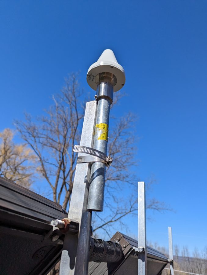
We have several of these nice Panasonic GPS antennas left over from various installs. I pressed one into service on the roof of my house.
Panasonic CCAH32ST01 GPS antenna
I think a high-quality antenna is pretty important to get consistent good performance from this setup. There are three slight problems, however. Unfortunately, this antenna has been discontinued by the manufacturer. Also unfortunate, the GT-7U boards have one of those little IPX RF connectors. Fortunately, I found a short jumper with an F SMA connector. Finally, it requires +5 VDC and the GT-7U runs on 3.3 VDC. The pi does have a 5-volt rail, so I used this 2-way power divider to feed 5 volts to the antenna from one port and the received RF from the antenna goes to the GT-U7 from the other port.
If you are interested, here are the commands to get this thing running:
sudo apt get update
sudo apt get upgrade -y
sudo apt install pps-tools gpsd gpsd-clients chrony
The next step is to make sure the serial port is turned on and enable the ssh login shell since this is going to live in the basement and I don’t want to run down there to fool around with it.
sudo raspi-config
Then go to interface options, serial interface, and enable. The login over the serial interface can be left off. If ssh access is needed, enable ssh, then exit.
Once those packages have been downloaded and installed, some config file editing is needed. You may use whichever method you like, I tend to use nano. First, the /etc/config.txt and add the following to the file:
The uart needs to be enabled if you want to receive NMEA data (NMEA stands for National Marine Electronics Association) It is helpful to see if or how the GPS is working.
Next, the /etc/modules and add:
'pps-gpio'
Reboot, then see if the pps module is working:
lsmod | grep pps
The output should look like this:
Next, there are a few more configuration files that need to be edited.
/ect/default/gpsd – there is a default file that comes with the package, it needs to be modified to start the daemon automatically and look for the pps signal on ttyS0.
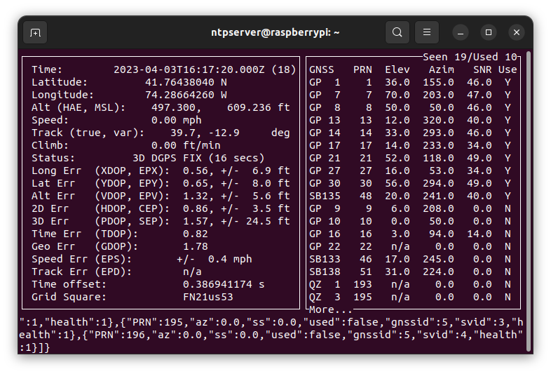
Now check and see if the GPS module is working by typing cgps or gpsmon. The output should look something like this:
It did not take the module too long to find and lock onto GPS. If you don’t see something like this in five minutes or so, go back and check your wiring, and make sure that the data connections are made right. The GT-U7 has a little red LED that is lit when the PPS pulse is not being sent. If this light is not on at all, check your power connection. If it is on steady, check your antenna. If it is flashing, but you are not seeing any output in cgps or gpsmon, check your data connections.
Next and last configuration file is the /etc/chrony/chrony.conf file. At the top of the file, I added the following lines:
#custom lines for PPS
server time-a-g.nist.gov iburst
server time-d-g.nist.gov
server 3.us.pool.ntp.org
server time.windows.com
server time.apple.com
# add refclock pps
refclock SMH 0 delay .1 refid NEMA
refclock PPS /dev/pps0 refid PPS
#my home network
allow 192.168.1.0/24
Leave the rest of the file alone. Basically, the time servers are added to compare the GPS time and act as a backup. The hosts on my home network are allowed to query this host and use it as an NTP server.
Restart Chrony:
sudo systemctl restart chrony
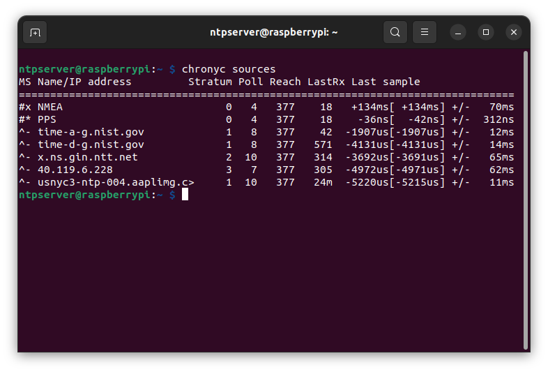
Wait a couple of minutes and check the chrony console to see what is happening: chronyc sources. Should look something like this:
This was after the server had been running for a day. Chrony is great because it measures the hardware performance and creates a delay file. This is used to anticipate any hardware-added delays that the system might have. The last sample column is of interest, the number indicates the offset between the local clock and the source at the last measurement. The far column is the margin of error or greatest variation +/- of the expected values. A value of 0.0000000042 seconds or 0.042 microseconds is pretty good for an $11.00 piece of hardware. Now every host in my house is syncd to satellite within 0.042 microseconds, in lockstep through the time-space continuum.
If I were to do this professionally, I would use better hardware. I think the pi 4 has better serial and ethernet interfaces, more RAM, and a quad-core processor. Last I looked they were $75.00 at Newark.
The GPS module was the cheapest I could find on Amazon. I am slightly concerned about the longevity of this device. Perhaps it will run for a long time, or perhaps not. A quick search brought up several “hats” (plug directly into the 20-pin header). These range in price from about $30.00 to $60.00. What is required of any GPS module is 1PPS output. The configuration would be about the same although some use GPIO 4 instead of 18.