Anytime a new transmitter is installed or major changes to an FM transmission system are implemented, the performance measurements described in FCC 73.317 should be completed to ensure no interference to other radio services. This is becoming a larger issue with the advent of LTE and 5G mobile data. These services along with E911 and other mobile services are often co-located at FM transmitter sites.
The FCC stipulates that emissions removed from the carrier by more than 600 KHz must be attenuated 80 dB below the carrier. These days, that is not enough. We have had issues with older tube-type transmitters interfering with cellular and mobile data service, even though they met or were far below the FCC specification. The first in, first out rule also didn’t seem to matter either. Those mobile phone providers paid a lot of money when they purchased chunks of RF spectrum at auction, and the FCC will side with them if there is any dispute.
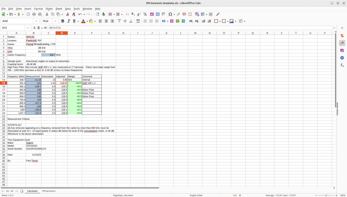
Having a record of measurements that show compliance with the FCC regulations can go a long way in heading off any future problems. I make measurements out to the 10th harmonic.
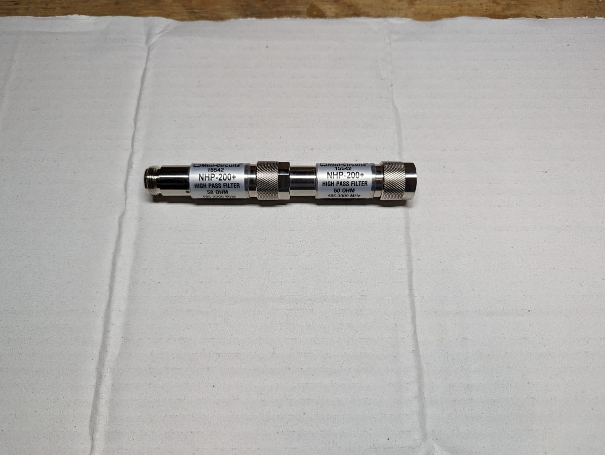
To get the best results, I have been using a couple of high-pass filters from Mini-circuits.
Mini-Circuits NHP-200+
These attenuate the carrier power seen by the spectrum analyzer by approximately 90 dB depending on the frequency. That allows the instrument noise floor to be lowered to -130 dB which should be well below any receiver noise floor being used by other wireless services.
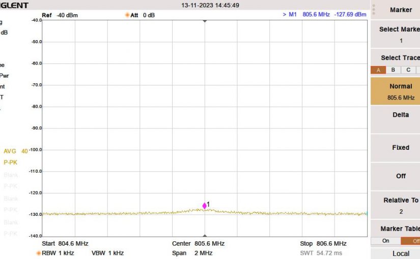
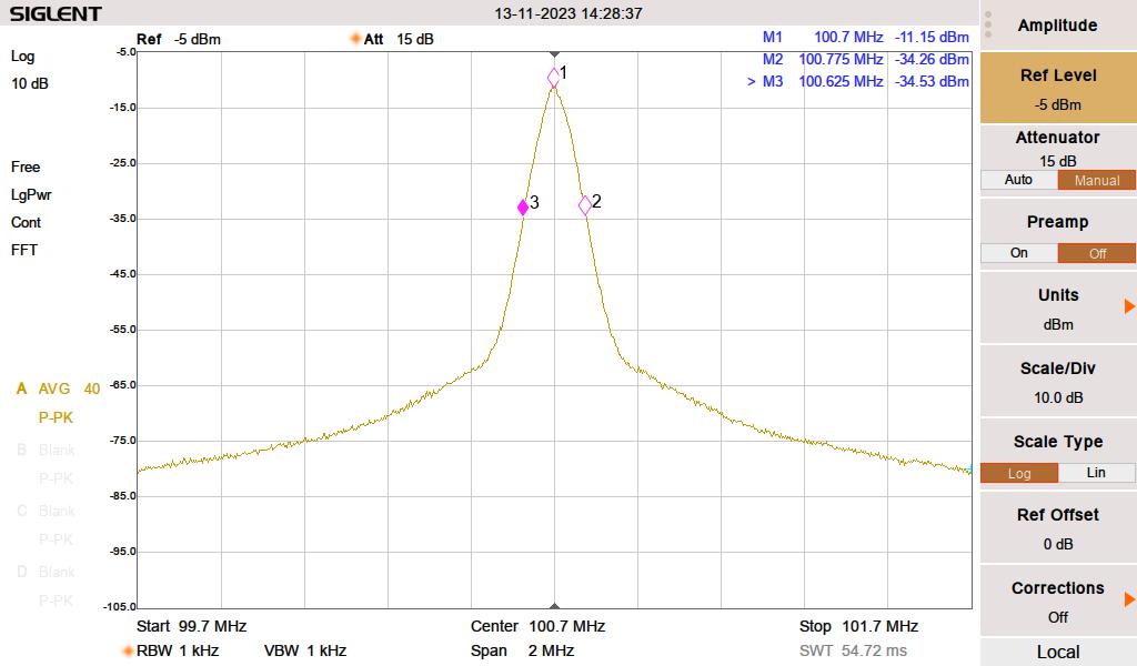
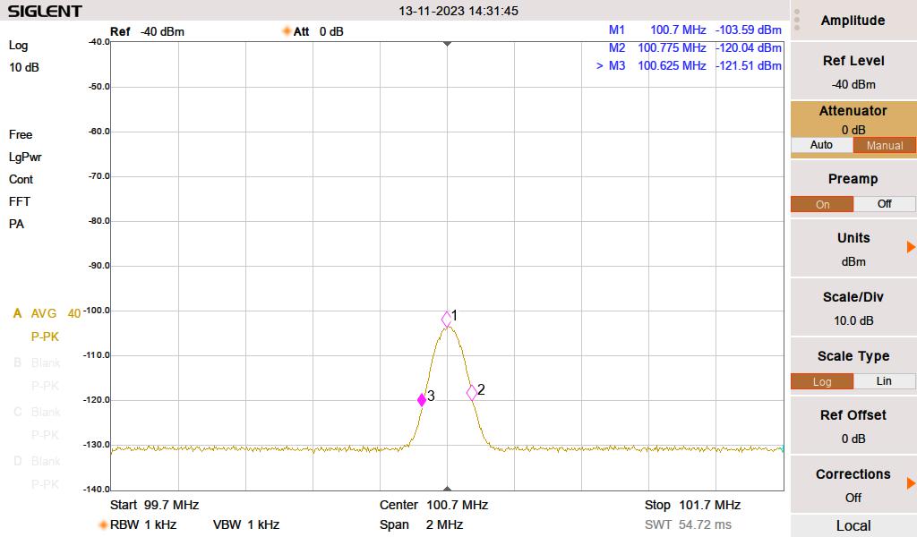
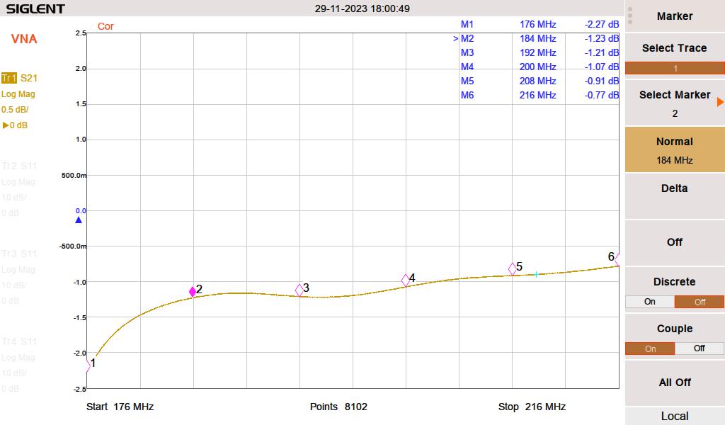
100.7 MHz no HPF100.7 with two HPF-200+ High Pass Filters
The carrier is attenuated by 92.44 dB. The rest of the measurements are made with the attenuation set to zero and the preamp turned on. For the lowest FM frequency, 88.1 MHz, the filters are on the edge of their shoulder at the 2nd harmonic. I measured the return loss and found that they matched the manufacturer’s datasheet.
Mini-circuits HPF-200+ X 2, 176 – 216 MHz S21 Return loss
That loss is counted as attenuation for the second harmonic. For the rest of the harmonics, I used 0.5 dB attenuation, which represents connector loss. I could have also measured the cable loss at each harmonic, but that seems unnecessary, given several of the readings were below the noise floor.
To speed things along, I made this handy Excel spreadsheet, which does all of the calculations for me:
I like these types of posts. Many people are intimidated by component-level repairs. I write this to show that it is possible, with minimal test equipment and easy-to-understand directions, to make repairs and get things back in working order.
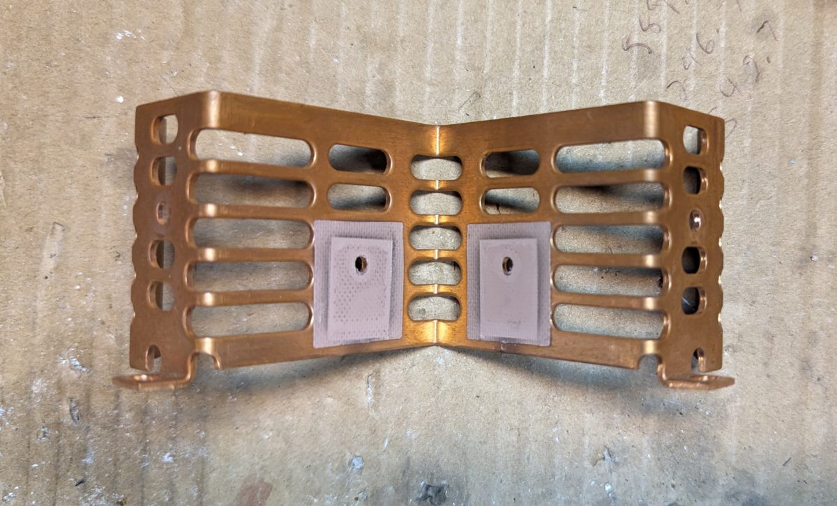
Every year, we lose two or three RF amplifier modules from the DX-50s. Normally, this happens after a thunderstorm. Sometimes it is a spontaneous failure.
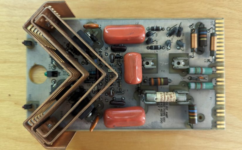
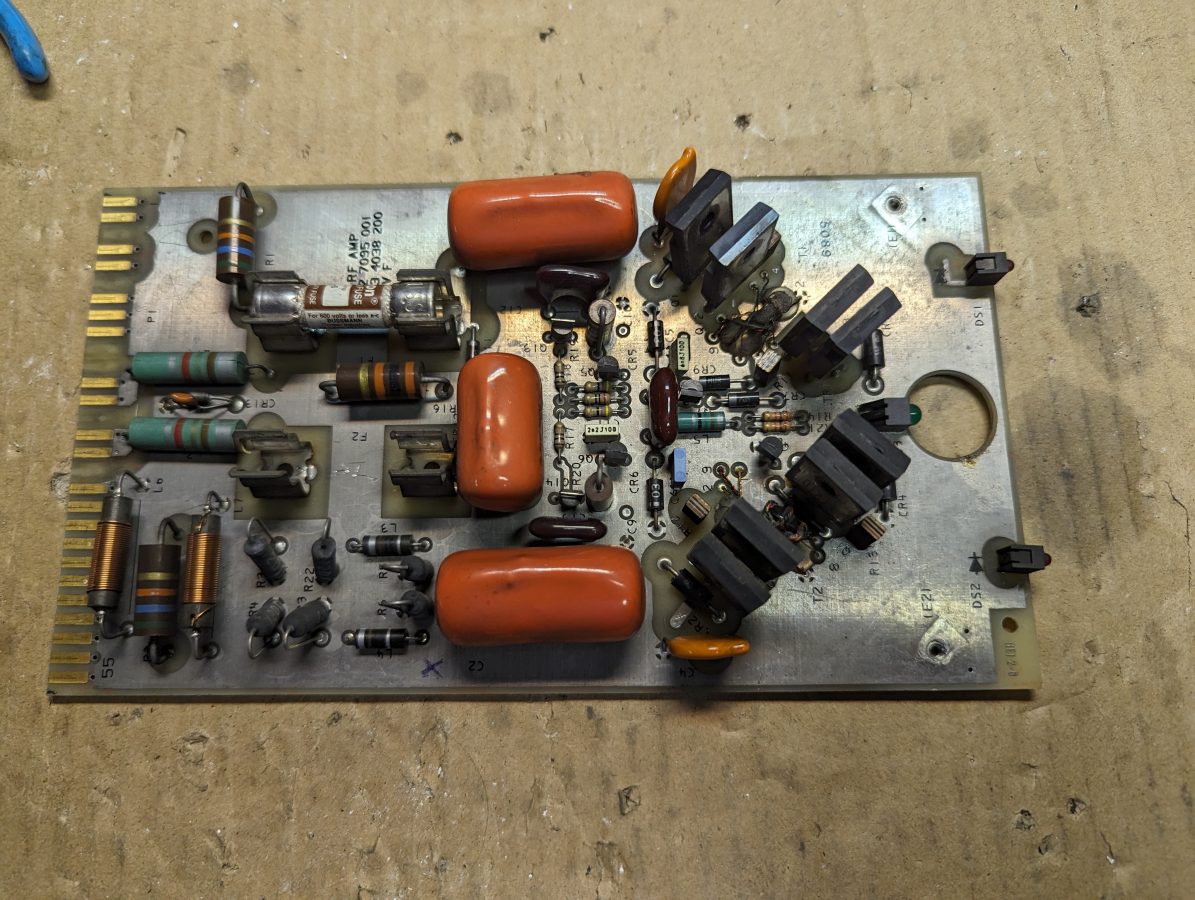
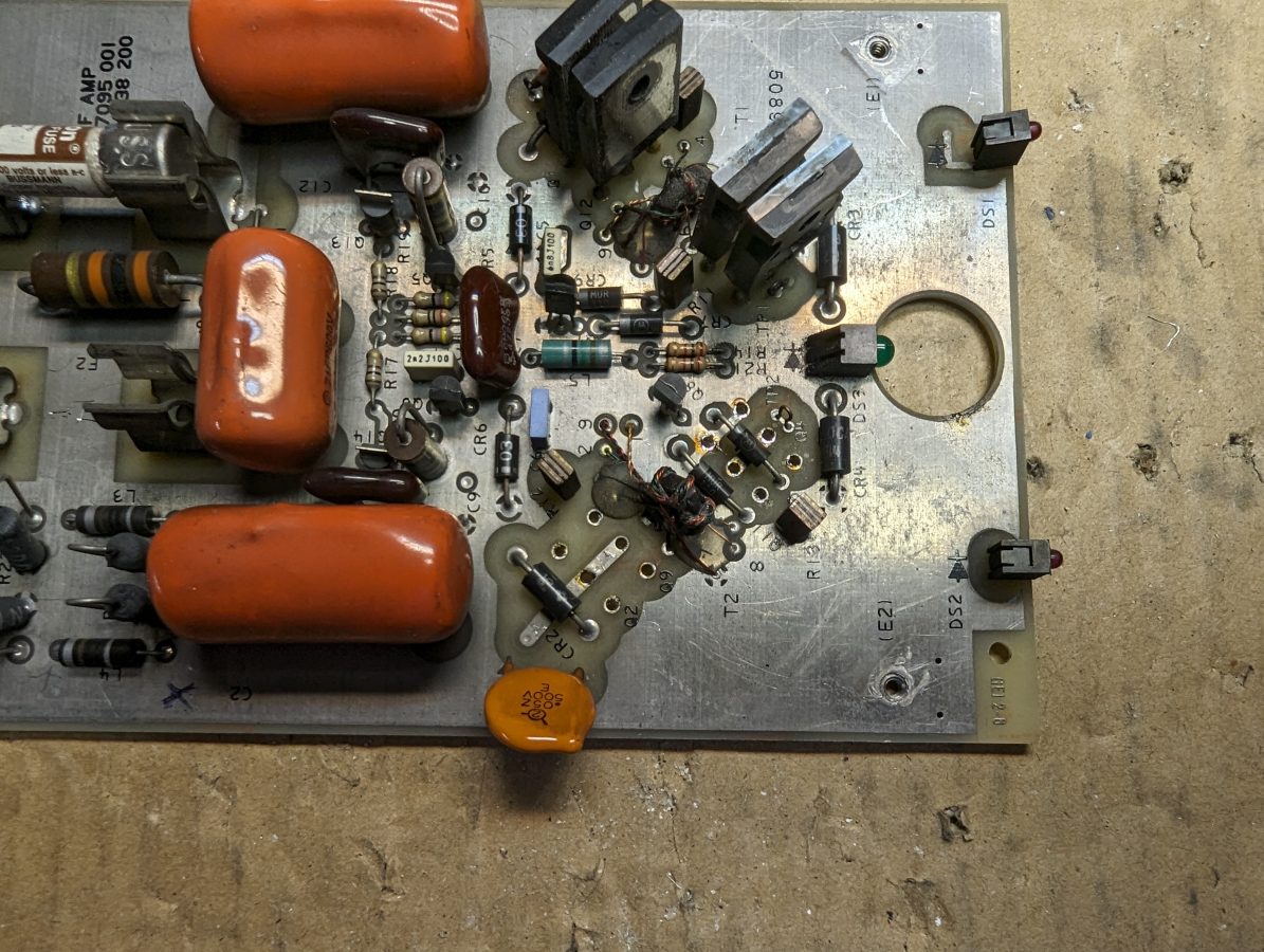
The project starts here; faulted RF module
These are fairly simple medium-wave RF amplifiers. There are no adjustments or tuning circuits on the amplifier board itself. They use eight IRFP-350 RF devices. There are two fuses to protect the transmitter power supply against device short circuits. If a fuse blows; Section C, RF amplifier Modules, of the DX-50 manual has a good troubleshooting guide. There is a very good chance that one or more of the RF devices is bad. Unfortunately, they have to be removed to be tested.
Gates Air recommends that if one device is failed, all four devices from that section are replaced at the same time even if they test good. The IRFP350s are inexpensive devices and it is easier to replace everything at once. The Mouser Part number is 844-IRFP350PBF and they are $3.81 each as of this writing. The PBF suffix means it is lead-free.
The other part that can be bad, but it is unlikely, is the TVSS diode across the gate and source (CR1-4). These are inexpensive as well. Mouser part number is 576-P6KE20CA and they are $0.38 each. It is good to have a few of these on hand.
Heatsink removed from the module
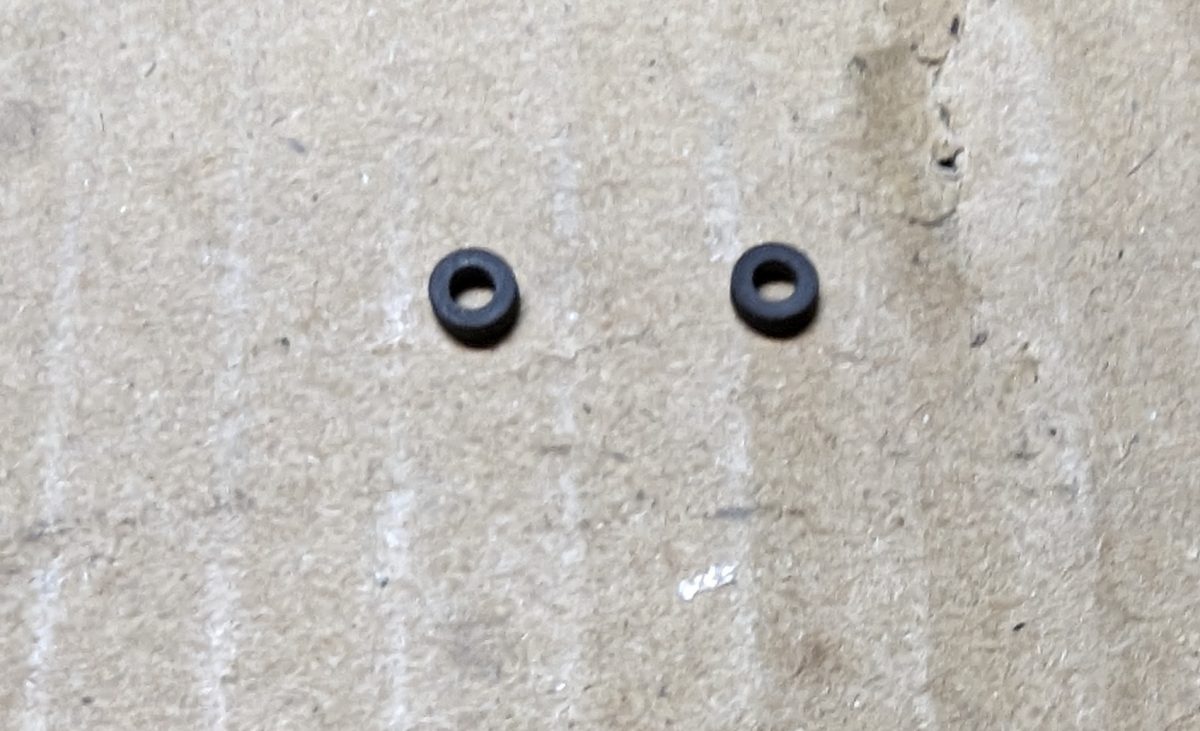
The most difficult part of this is dealing with the heat sinks. The devices get stuck to the heat sink pads after so many years, so it takes a little effort to get them separated. The manual recommends gently prying the device away from the heat sink with a small screwdriver. They can be reused if you are careful and do not rip the insulator pad. However, if the insulator pad rips, it needs to be replaced. Mouser part number 739-A15038108 ($0.86 each).
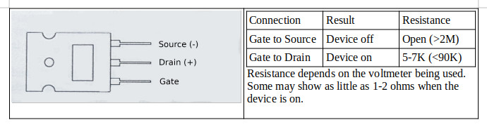
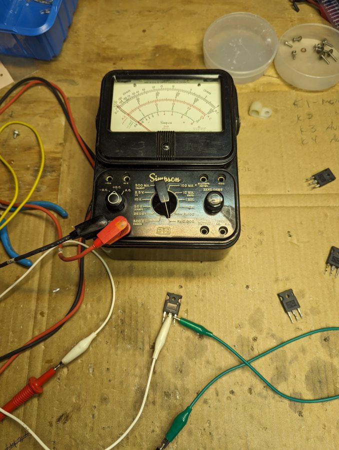
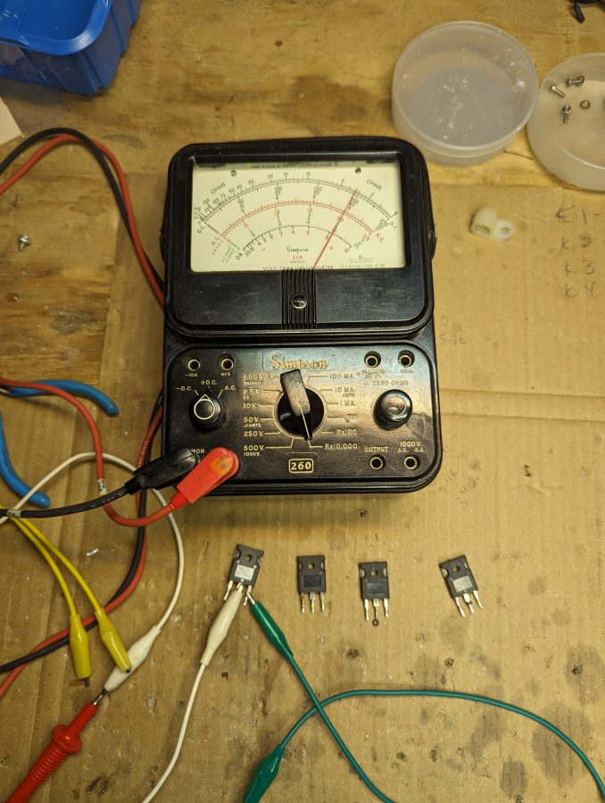
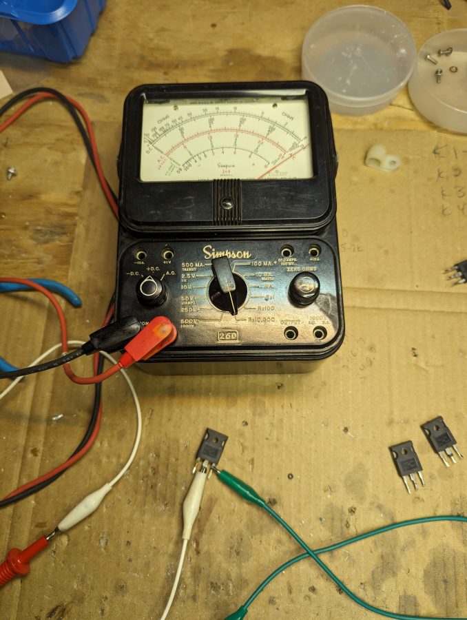
To test each IRFP350 after it has been removed, use either a DVM with greater than 3 VDC on the resistance setting or a Simpson 260 on the Rx10,0000 range. Connect the positive lead to the Drain, the negative lead to the Source, and then use a jumper connected to the Gate to turn the device on or off. Alternatively, you can use a 9-volt battery to turn the device on and off.
If the device does not turn on or off, it is defective.
The TVSS diode should measure open (>2M) in both directions. Anything other than that, the unit is defective and needs to be replaced.
DX-50 module, heatsinks removed
The first step is to remove the heat sink. I used a small screwdriver under the leads to gently pry the MOSFETS off of the heat pads. If you are careful, all of the heat pads will survive. Once the heat sink is off, I remove all four of the suspected MOSFETS. The leads are heavy gauge, so it takes a little bit of work with the solder pump and solder wick. I tested each MOSFET and found one shorted unit, the other three test okay. However, since these are inexpensive devices, I replaced all four.
DX-50 module, MOSFETS removed
Good device:
Device offDevice on
Bad device:
Device shorted
Assembly is in reverse order. Make sure that none of the insulating pads were torn during disassembly. I like to get everything attached to the heat sink before soldering the leads. It helps with lining everything up. Take care and make sure that the ferrite beads on the drain leads of Q3,10 and Q4,11 are re-installed with the new devices. These are necessary to prevent high-frequency oscillations.
Ferrites
Of course, the final test is in the transmitter. Generally speaking, I test the standby transmitter into the test load every two weeks. This is done in conjunction with the generator load test so as not to spin up the demand meter.
There are many times when some mathematics is needed in this profession. For one-off situations, the calculator applications found on most smartphones will work just fine. However, sometimes the calculation is complex or is needed to be repeated many times. Excel Spreadsheets have many mathematical functions built in. Plugging a formula into an Excel spreadsheet is a handy tool.
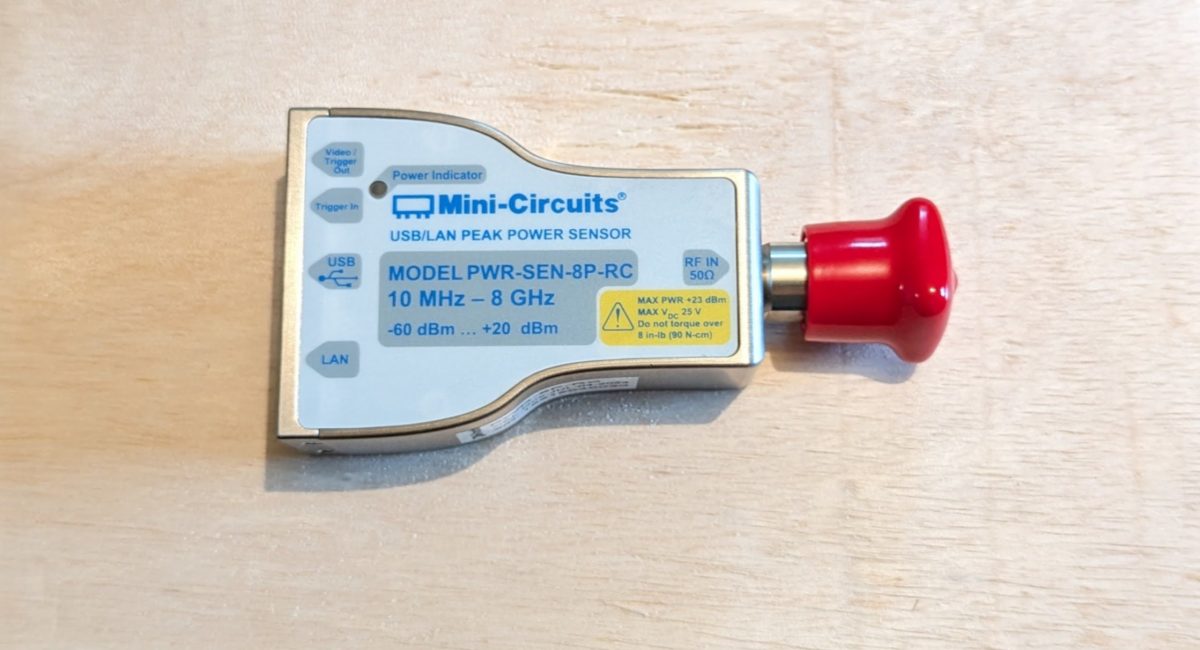
I recently acquired this rather nice precision power meter:
Mini Circuits precision power meter
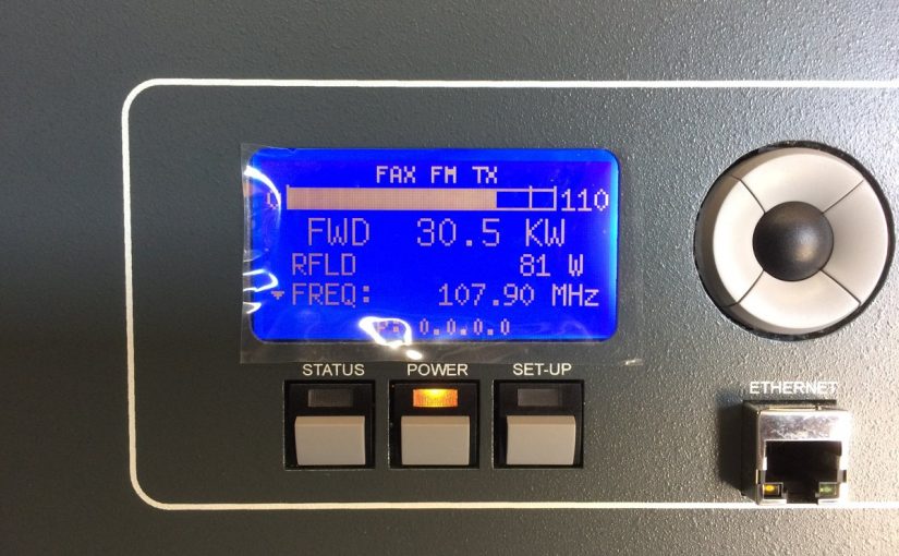
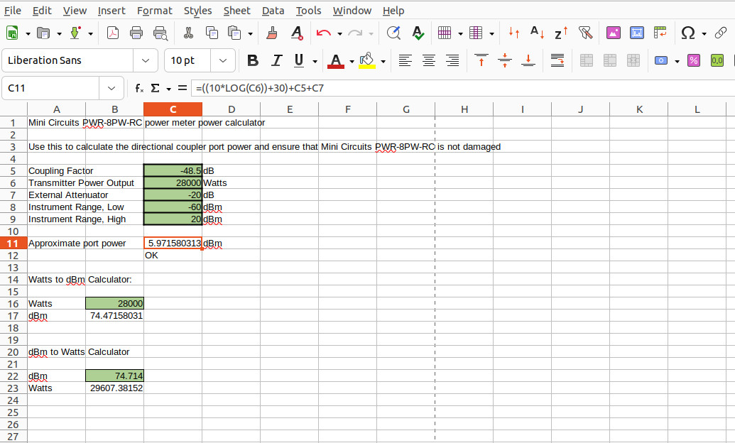
It has an input power range of -60 to +20 dBm with a stern warning not to exceed +23 dBm. Since we will be using this for a variety of applications, I thought it might be useful to know approximately how much power will be presented to the instrument in any given situation. For example, we are installing a 30 KW FM transmitter soon. The directional coupler that will be used has a coupling factor of -48.5 dBm. The TPO is 28,000 watts.
The formula to convert Watts to dBm is dBm=10 X Log10(Pw) + 30, where Pw is power in Watts. Thus dBm=10 X log10(28000) + 30 or 74.4715 dBm minus the 48.5 dBm coupling factor which is 25.9715 dBm. That is too much input for this power meter. A 20 dB attenuator will need to be used.
Since I will be using this meter in other places, rather than doing that calculation over and over again, why not build an Excel spreadsheet? That would make it easy to check.
A simple Watts to dBm calculator in Excel looks like this:
=(10*LOG(C6))+30
This is copied into cell C11. C6 is the cell in which the Transmitter output power in watts is entered. The other cells contain the coupling factor (C5) and external attenuation (C7) In application, it looks something like this:
Excel spreadsheet power meter calculations
You can arrange these any way you like, just change the cell numbers to suit your needs.
I like to make the data entry cells green. You can lock the formula cells so that the formulas don’t get changed accidentally. Below the Approximate port power cell, is the IF statement that will return either a “LOW”, “HIGH”, or “OK” depending on the result value in C11. That looks like this:
It would be very easy to make a system gain/loss calculator for using the licensed ERP to calculate the proper TPO.
Other examples of useful Excel spreadsheet formulas:
To convert from dBm to watts:
=10^((B22-30)/10)
B22 is the cell in which the power in dBm is entered. These can be any place you want on the spreadsheet.
Radio Frequency to Wavelength in Meters:
=299792458/B10
Where B10 is the cell in which the frequency in Hz is entered. 299792458 is the speed of light (Meters per second) in a vacuum. If you wanted the input frequency to be in kHz, simply move the decimal point for the speed of light three places to the left, e.g. 299792.458. For MHz move the decimal four places to the left, GHz five places, etc.
Convert electrical degrees to Meters:
=(299792.458/B10)/360*B11
Where B10 is the frequency in kHz and B11 is the number of electrical degrees in question.
Where B11 is the air temperature in degrees Celsius and B12 is the frequency in Hz. Room temperature is normally about 21 degrees Celsius (about 70 degrees Fahrenheit). Humidity and altitude can also affect the sound wave velocity, which will affect the wavelength.
Base (or common point) current calculator using base impedance and licensed power:
=SQRT(B12/B11)
Where B12 is the License power in watts and B11 is the measured base impedance of the tower (or common point impedance of the phasor).
Convert meters to feet:
=B11/0.3048
Where B11 is the length in meters
Convert feet to meters:
=B12*0.3048
Where B12 is the length in feet.
Convert degrees F to degrees C:
=(B11-32)/1.8
Where B11 is the degrees Fahrenheit
Convert degrees C to degrees F:
=(B12*1.8)+32
Where B12 is the degrees Celsius. In this case, the order of operations will work without the prentices but I kept them in place for uniformity.
Convert BTU to KW:
=B11/3412.142
Where B11 is the BTU/hr
Example of an Air Conditioner load estimation:
=(B11*B12-B11)*3412.142
Where B11 is the TPO, B12 is the transmitter AC to RF efficiency. The output is in BTU.
You get the idea. Yes, there are smartphone applications as well as online calculators for most of these functions. However, I have found smartphone apps are becoming more painful to deal with as time goes on, mostly due to the ads. App developers need to make money, and you can buy apps for things that are often used. However, it is nice to have these types of calculators available offline. Besides, it is fun to play around with Excel formulas.
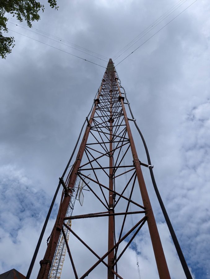
This is the original tower for WKIP, but not the original antenna. It was put up circa 1960 or so and like many towers from that era, has hollow legs. Thus, after 60 years or so, it is deteriorating from the inside out.
WKIP tower #1
This was part of a two-tower directional array. It is odd that a class C station on 1,450 KHz would have a directional antenna at all. Even stranger still, it was directional daytime, non-directional night, both at 1,000 watts. The reason for such an odd situation; the station was co-owned with WGNY in Newburgh and the daytime coverage contours would have overlapped without a directional array. The taller tower is 215 degrees tall with top loading. During the daytime, the pattern goes to the North and it covered very well.
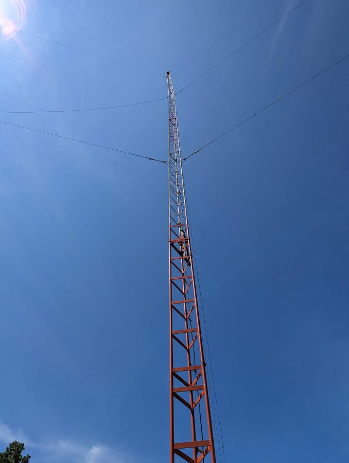
Vertical Bridge, the tower owner, decided it was time to replace the aging structure with a monopole. They are completing the project this summer. Our part is to move WKIP to the shorter tower and put up a temporary FM antenna for the translator. Once the project is completed, WKIP will operate from the shorter tower (which is 85 degrees) permanently, getting rid of the now unnecessary directional antenna on a class C channel. The translator antenna will move back to the monopole, once it is put up.
Problems… Yes, we have a few of those…
WKIP tower #2 with broken guy wire
First, the short tower had a broken guy wire. Actually, the guy wire was fine, but the lowest grip connecting to the equalizing plate was rusted through. It is fortunate that this was discovered because the upper guy wire was getting ready to let go too. Northeast Towers was able to replace all of the grips on that set of guy wires and re-tension the tower. They did a full investigation of all of the other anchors prior to any climbing. This is in a swamp, which has flooded several times over the last few years.
Tower #2, guy wire repaired, Scala FMVMP translator antenna mounted
Next, the temporary FM translator antenna was hung on the tower. It was thought that the 3/8 sample line from the old AM sample system could be used as a temporary transmission line for this system. Unfortunately, that line turned out to be 75-ohm cable TV drop line and was not suitable for transmission of VHF. We had about 600 feet of leftover 3/8 sample line (Cablewave FCC 38-50J) from a decommissioned AM site, so we used that instead. It has quite a bit of loss on VHF, however, for temporary use, it will work.
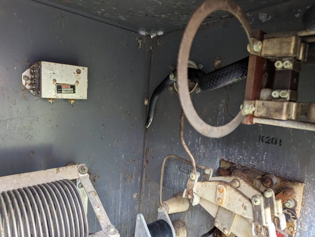
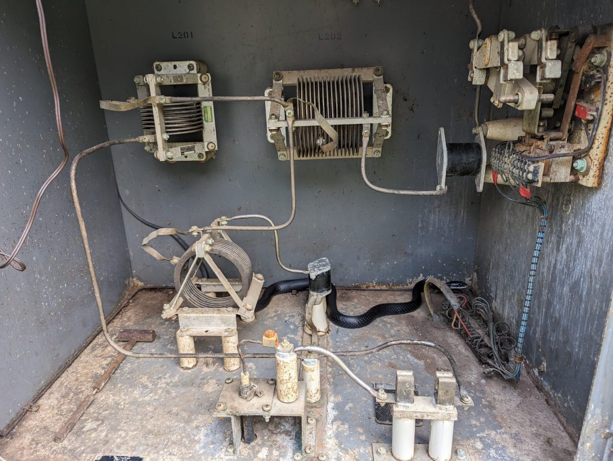
Black Rat Snake, harmless and helpfulBlack Rat Snake
Next, it seems this black rat snake had taken up residence in the ATU cabinet. The bottom of the ATU was full of mouse nests going back many years. One of our employees dutifully cleaned out the mouse nests unknowingly under the watchful eyes of this snake. Only after he was done, did he see the snake coiled up on the disused current meter shunt. There was a mild freakout for several minutes, but the snake left on his own and we got back to work. The black rat snakes are helpful to have around, but perhaps best if he stays outside of the ATU. We will seal up the entryway for the coax, which seems to be where all the critters are coming in.
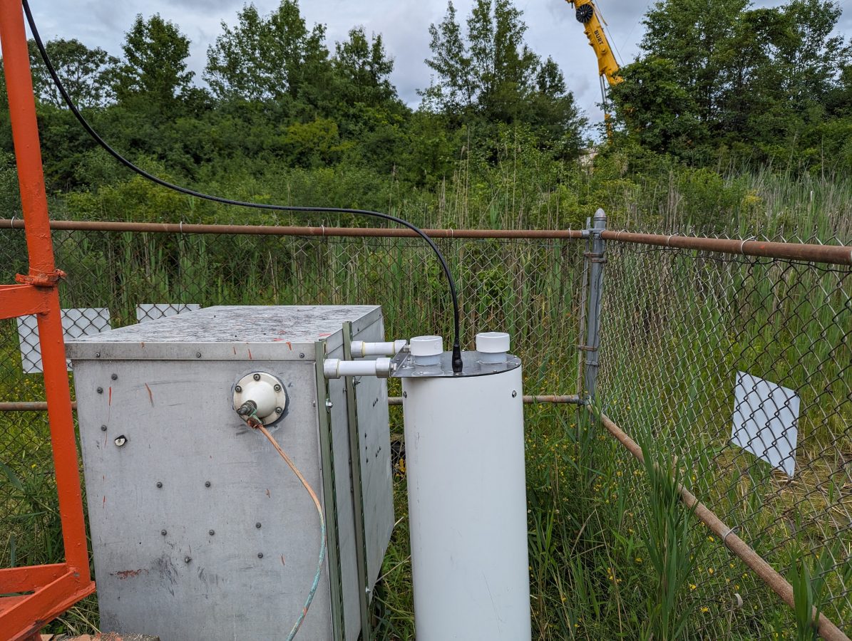
Kintronic ISO-130-FM-N Isocoil
This Kintronic Isocoil was mounted to the back of the ATU with unistrut. Even though this is a temporary installation, I have found that sometimes temporary things can last much longer than anticipated. Besides, it was easier than trying to use pressure treated 4 x 4 lumber.
Next, we measured the ATU with the fancy machine (Agilent E5061B network analyzer). In theory, the ATU input should be 50 ohms to match the incoming transmission line. No, instead it was 38 Ohms -j20.
So, a little bit of a retune was required. With the fancy machine, we were able to get it to 52 ohms -j9 or so. This is good enough for now, there will be numerous cranes in the air and the station has an STA to run at 250 watts for the project’s duration. After the new monopole is up, we will measure the base impedance of the tower and tune up the ATU for 50 ohms and then return the station to full power at 1 KW.
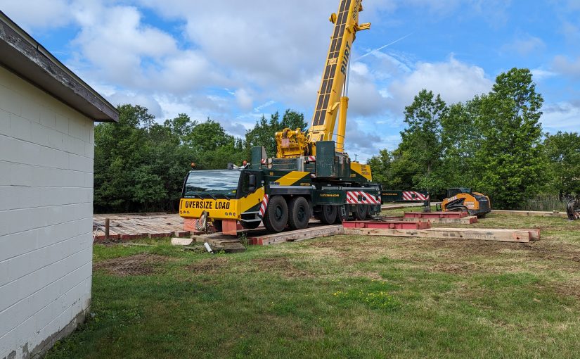
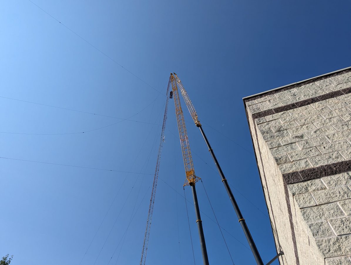
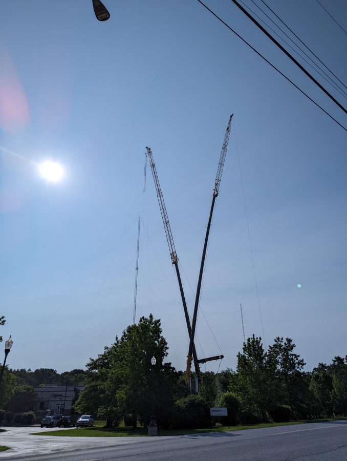
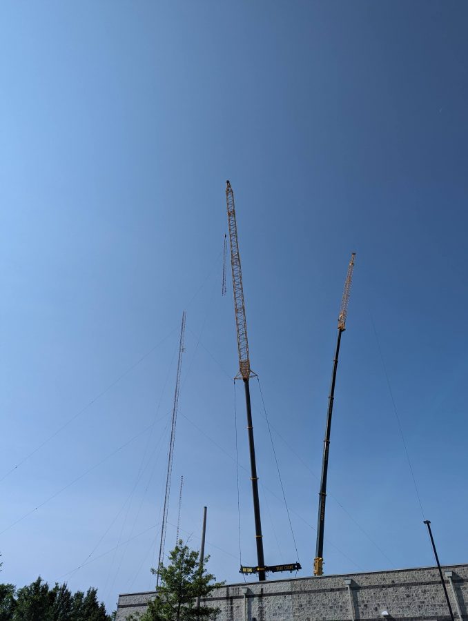
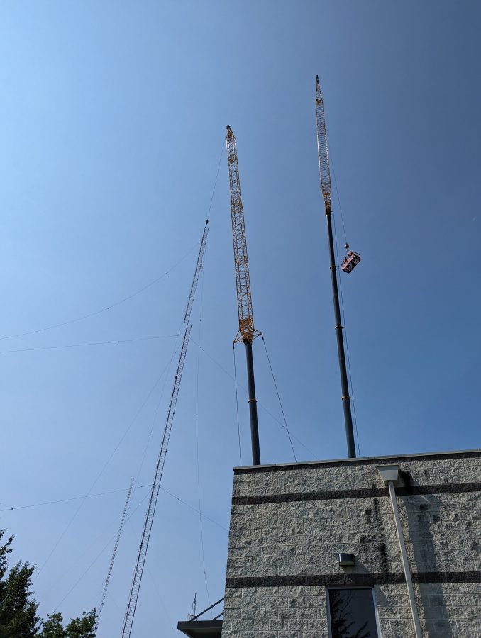
Smaller crane, used to assemble the larger cranes
The old tower coming down:
Top section and top loading wires separated
Two cranes were used; one to hold and lower the tower section, the other to lift two tower workers to cut away the sections. The tower was deemed unsafe to climb, therefore it had to be removed like this. It was also unsafe to drop because of the proximity to the studio building and the other tower, which is being retained.
Top section being loweredNext section removed and being loweredNext section removed
You get the idea. These tower sections and guy wires were cut up and put in a scrap metal dumpster. They will be recycled into something else.
Now, they will work on removing the old tower base and putting up the monopole. Once that is done, we will tune up the AM on the short tower and get it back to full power.