I’ve been away working in Burlington, VT (WVMT, 620 KHz, Burlington) for the last coupla, installing this nifty Nautel transmitter:

I like the Nautel units, both AM and FM; they are well-designed, well-built, rugged transmitters. I have lost track of how many of these units we service in the field, partly because they are becoming pretty much standard equipment at all of our installations.

The transmitter it is replacing is a Continental 315R-1, which is based on the Collins Power Rock design. It is a PWM transmitter with a 15,000 volt power supply. In their day, these were not terrible transmitters, however, like their Harris MW-5/10/50 PDM brethren, frequent thorough cleaning is required to keep the dirt/dust from arcing over. Unfortunately, it is becoming more and more difficult to obtain parts for these units. This transmitter was installed in October of 1983, thus, almost thirty years of service is quite enough. This unit we did not cut up and scrap, rather, it is sitting by the back door, waiting for any takers.

The interior of the Continental 315-R1 transmitter. Modulator section is on the left, RF section is on the right.
The good news is, WVMT is another one of those “successful AM station” stories. You know, the kind of station that has local programming, local sports, news, community presence and most importantly, makes money. For all those diligently studying the “AM Problem” for the up and coming NAB conference this April, here is a clue: It’s the programming…
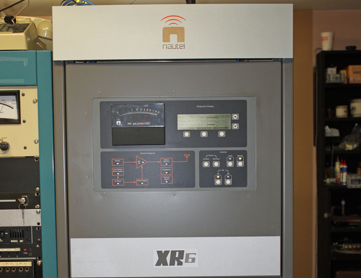
This is the Nautel XR-6 on the air. Positive peaks, anyone?

We turned that down a little bit. Also, the station does not run AM stereo, the AM stereo mod monitor is simply a usable relic of a bygone era.
WVMT is noted as the first radio station licensed to the state of Vermont, signing on on May 10, 1922. It has a three tower directional array located down in the swamp. For some idea of perspective, it is 1,150 feet (350 meters) from the transmitter building to the center tower, the towers are 411 feet (125 meters) tall spaced 405 feet (123 meters) apart.

WVMT antenna system from back of transmitter/studio building. That is a long walk over rough terrain in the middle of the night or anytime really, but especially in the middle of the night.


It is also one of the most difficult to take a picture of. Their FM, however, is really easy.
My picture of WVMT is from a overlook in Burlington, where I could also see the three 1390 towers as well.
Out of curiousity why would they blow off that wonderful Continental 815-R1 and keep what looks to be a Gates BC-5H or HA (neither were really great performers though the HA did have a 10 KW power supply and audio driver deck)on the left side of the phasor? Too hard to cut up? I hope it can go to someone who really appreciates it or already has another
@Mike, even the picture above with the descriptive distances does not do justice to the scale of the antenna array
@Chris, it is indeed a BC-5HA, which seems to have better availability of parts than the Continental. The only thing that makes me nervous about the BC-5HA are the audio driver board output transistors (Q4-5), however, we have some spares of those. Given the past reliability of the Nautel products, I don’t anticipate the BC-5HA will run very much
I’ve heard WVMT in Springfield, MA before. It seems to do really well to the south for a signal from the array.
Hey Paul, It’s a BC-5H. I spent many a night working on that beast including upgrading the RF driver…. When I came to work there as chief in 1978, they had the BC-5H and a 5A.
If folks are interested, I have pictures somewhere here of the antenna system replacement. Since this system is located in a swamp, the bases were constructed using piles. They go down 90 feet before hitting anything solid. Anchor were done by Chance Anchor. Screw type. There are several in excess of 200 feet down.
It’s an environmental wetland, so we did all the construction in the winter as we were not allowed to build any road. We actually just packed down the snow so it froze and used sheets of plywood to spread the load of the drilling machine.
Probably the toughest part was pull testing the anchors. Imagine having to pull 90,000 lbs while sitting on a surface that wasn’t close to solid.
Mike
Hey Mike, sure, if you want to sent those pictures along, I’ll tack them to the end of the post. It is amazing the number of AM stations built in swamps, I suppose it is a use for otherwise un-buildable land. I’ll have to dig some of the WLNA photos out that I found when we cleaned out the transmitter site in Peekskill, same situation, towers in a swamp, constructed during winter, etc.
Mike, since the replacement involved environmental wetlands it sounds 1980’s +, what was the original WCAX array that this replaced.
Hi Chris,
Yes, the 80’s. The original WCAX array was from the 40’s. It was a terror to put it mildly. The towers were 66.9 degrees electrical! Base currents were through the roof and it was unstable as all get out. The phasing system was built in one small cabinet and the interaction was phenomenal.
The original tower bases are still there. The new doghouses were built on them. All the original construction was at ground level. Being in a swamp connected to the Winooski river, it flooded every spring. The station would go off the air as the water rose over the base insulators. It was novel to watch the Common Point rise as the water came up. I was usually able to keep the station running by unplugging towers 2 and 3 and running on just tower 1 which miraculously stayed just above the water.
The tower bases themselves were rafts. So I’m told, cedar logs were dumped into a hole until they didn’t sink anymore and then a concrete cap was poured over that. This caused them to ‘float’ during the floods! The anchors were under poured (too small). What would happen in the spring is the floods would come, the anchors would float up slightly. Guys wires would loose tremendously and the whole tower would sway!
We would head to the swamp and tension the guys just enough to get us through the incident. What would then happen is the anchors would settle. When they did, they moved in closer to the tower base because of shortened guy cables. Can you say “underguyed” tower?
Transmission lines were foam and when we replaced them, I found where water had gotten into the line in numerous places and actually exploded the jacket. But being at 620 kHz, you can get away with all sorts of things. I remember one night keeping us on the air with booster cables from my car. But that’s another story.
Mike
Speaking of hearing WVMT is Springfield, MA the array is a figure 8 with the major lobe heading up into Canada.
When we did the new phasing system, I was working with Harry Seabrooke and Jim Kemmen from Silliman and Silliman. We set the array with parameters from the FCC CP.
Shortly after going on the air, we got all these fabulous signal reports from down south. MA, CT etc. This was before we began the proof.
I looked at the license carefully. The FCC had mixed up tower 1 and 3 so the array was upside down. Our major lobes was headed South.
We fixed that the next day.
Mike
Have you had any takers for the Continental, I’ve been looking for a tube AM transmitter I can convert for HAM operation.
Thanks Rich
Richard, the transmitter has been claimed. Just for reference, this particular transmitter is difficult to retune and has a 15KV power supply. For amateur radio operation, I would recommend something that has a modulation transformer, as they are simpler and easier to deal with than PDM transmitters.
Hi Paul, thanks for the information I’ll keep that in mind. I hadn’t realized there would be difficulties retuning something I will have to watch out for.
Can you tell me what are the main problems retuning one of these?
Thanks
Rich
Richard, The main problem with these transmitters is the 15,000 volt power supply. Certain parts of the transmitter (oscillator card, PWM card) are isolated from ground and float at 15 KV potential. I believe more than one engineer has been killed trying to tune these things. If you intended on stripping out the cabinet and using the parts to make a big linear amplifier, that would be better. I would not recommend this particular model transmitter be retuned by somebody that does not have experience with PDM/PWM.
I drove by that site multiple times for a job I had a number of years back… never gave them all that much thought (other than “oh look, another AM array in a swamp”). This article and the great comments posted to it make for one of the most interesting and meaningfully-informative things I’ve read in quite a while! Thanks to everyone who has posted!