The Continental D323C medium wave transmitter

I found a 1981 Continental Electronics equipment catalog at an old transmitter site. These finds are great if one is interested in history and looking at the way things used to be done.  This particular transmitter is a 2,000 KW (2,000,000 watt) medium wave unit:

Continental Electronics D323C, Circa 1981

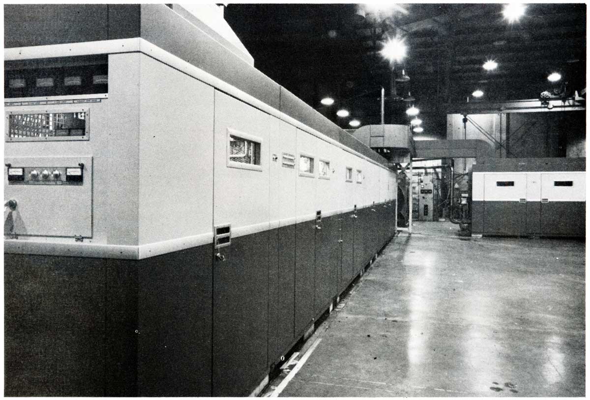
I believe most units like this were destined for use by government broadcasters in either the middle east or Western Europe.  I know there were several 1,000 KW medium wave stations in West Germany at one time.   The Continental transmitter is basically two 1,000 KW units (323C) combined.  They used a modified version of Doherty modulation, that is called “Screen and Impedance,” which accurately describes how it works.  More information from the Continental Catalog can be found here: Continental D323C.  The tubes (or valves depending on where you are located) used in the D323C were 4CW25000A tetrodes as modulators and IPA the final was a pair of X2159, which is an impressive tube.

EIMAC X-2159 water cooled power tetrode
EIMAC X-2159 water-cooled power tetrode

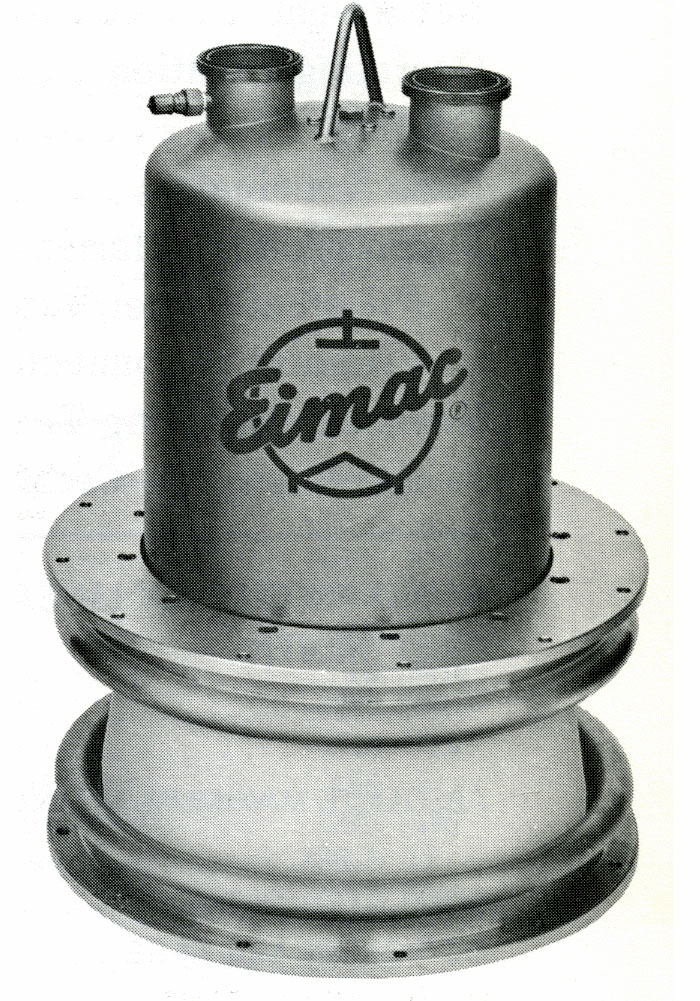
The tube sat anode up.  The filament, grid, and screen connections are underneath.  Cooling water was pumped through the two connections on the top at about 130 gallons per minute depending on the plate dissipation.  With a 30° C rise, that equals about 96,000 BTU per minute.  The D323C had a dissipation of 400,000 watts for the carrier tube and 240,000 watts for the peak tube (640 KW total) under 100% modulation.  That equals about 2 million BTU per hour.  Notice the lifting hook, this tube weight in at 175 pounds.  Tube date sheet here.

Continental no longer makes medium wave transmitters, their closest high powered broadcast product now is the 418/419 and 420 HF (shortwave) transmitters.  The 420D does a wimpy 500 KW using a solid-state modulator section.

I remember in the early 1990’s when I was at the Harris plant in Quincy, they were working on a 1,000 KW solid state DX series AM transmitter for Saudi Arabia.  It had to be liquid cooled, which added another layer of complexity to an already complex system.

I don’t know if there is much call for 2 MW medium wave transmitters anymore as there are more efficient ways to reach remote populations and I can’t even imagine what the electric bill would be like.

Zonecasting; the Technical Details

I saw this item many weeks ago, but, had not had time to look at it until now.  Geo Broadcasting Solutions has filed Petition for Rule Making (RM-11659) based on a system that divides the coverage area of major stations into smaller zones allowing for ad targeting of specific audiences.  They have coined the term “Zone Casting” to describe the scheme. It is covered by two US-issued patents filed by Lazer Spots, LLC: 20120014370 and 20110065377.  After a look at these two patents, it seems there are three possible ways to accomplish this Zone Casting Scheme:

  1. In the first described method, the main transmitter is broadcasting area wide and all the zone transmitters are muted.  An inaudible signal is transmitted to all units, the main transmitter is then muted and the zone transmitters turn on and transmit localized content.  After the local information is transmitted, the zone transmitters mute and the main transmitter resumes broadcasting.
  2. In the second described method, the main transmitter and the zone transmitters are broadcasting area-wide information.  The main transmitter ceases broadcasting area-wide information and the zone transmitters begin broadcasting localized information.  At the end of the localized information, the main transmitter and zone transmitters transmit area-wide information.
  3. In the third describe method, the main transmitter and zone transmitters are broadcasting wide area information with “capture ratio pattern.”  The main transmitter initiates an alteration, temporarily becoming a zone transmitter.  The zone transmitters then transmit localized content.  After the localized content, the main transmitter becomes a main transmitter again.

All of the transmitters are linked to the studio via digital STL systems, and content for the zone transmitters is distributed via IP network.  The transmitter frequencies are synced with GPS, similar to FM on channel booster stations.  Method number three includes possibly switching the transmitter output to a lower gain and or lower height antenna.

Zone Broadcasting Conceptual Diagram

Of the three methods, the first system will result in the fewest interference issues.  No matter which method is used, there will be interference issues between the zone transmitters and or the main transmitter where the signal strengths are equal and the audio is 180 degrees out of phase.  These can be moved around slightly by adding delay to the audio signal, but they will always be present.  More about Same Frequency Networks (SFN) and Synchronized FM signals can be found here.  While the zone transmitters are transmitting dissimilar localized information, standard capture effect rules apply.

The system has had limited testing in Salt Lake City, Utah (KDUT) and Avon Park, Florida (WWOJ), which according to the filing and comments, went well.

Geo-Broadcasting is applying to conduct a full test with WRMF in Palm Beach, FL.  The expected installation will include up to 22 zone transmitters.

Conceptually, tightly targeted advertising is not a bad idea.  Advertisers like it because they perceive a better return for their dollar.  The cost of such a system is not insignificant. Transmitter site leases run $1-2K per month, leased data lines, equipment, installation work, equipment shelters, etc will likely run several hundred thousand dollars or more.

If it gets approved by the FCC, it will be interesting to see how it works and whether or not the system is financially justifiable.

The Nautel NV-5 Transmitter

We are currently installing this sweet little transmitter:

Nautel NV-5 FM transmitter

Like its big brother, the NV-40 at WVPS, the NV-5 is a very cool transmitter.  I am a born skeptic, things like touchscreen displays tend to make me a little nervous, especially on a transmitter connected to a 350 feet tall steel tower right next to the transmitter building.  That is the one major difference between WVPS and this site; at Mount Mansfield there are many things between the transmitter and antenna, but in this place, not so much.  Even so,  Nautel makes a good product, so troubles are not expected.

The ground strap, AC power, remote control, and composite audio connections were all made without difficulty.  The result, new transmitter on the air:

Nautel NV-5 FM transmitter GUI

This unit is analog only, but the information on the spectral display is still useful.  The GUI uses Linux with a touch screen, which is a neat feature.

Nautel NV-5 FM transmitter controller board

In case the front panel GUI goes out, all transmitter controls can be accessed via push buttons on the remote control interface, which is the small board to the right.  The main controller board is on the left.

The Audioarts Air-4 Console

Aside from everything else, we have been working at WSBS, Great Barrington, MA installing a new Audioarts Air-4 console. WSBS is a small AM station (860 KHz, 2,500 watts day, 4 watts night) serving the Great Barrington area. They also have a 35-watt FM translator (W231AK) on 94.1 MHz which is highly directional.  During the day, the AM station has a much better signal than the translator.  After dark, the translator covers the downtown area fairly well.  WSBS has been on the air since December 24th, 1957 (Happy 55th anniversary!), broadcasting from a non-directional tower just east of town on US Route 7.

The format could be termed full service, in the old tradition.  Music, professional sports, local news, network news, and weather with coverage of special events like election night and so on.   The station does local very well, and as such, is profitable and has a great community presence.

WSBS control room console

The air studio console was this rather tired-out Broadcast Audio unit from the early 1980s.  It had certainly served its station well, but change was in the air, so to speak.  Actually, we were getting worried about continuing to service this unit, as parts had become scarce about ten years ago.

New WSBS control room console

Thus, we moved the air studio to the production room temporarily and removed all the old equipment and furniture.  We installed an Audioarts AIR-4, which is a pretty cool little console.  The AIR-4 has four built in microphone preamps, a telco mix minus feed, two program busses selectable VU meters and so on.   The control room rebuild project included a new counter top, adding extra microphones, headphone amplifiers, cleaning up wiring rat’s nests, installing new monitor antennas, rewiring a good bit of the rack room and so forth.

RE-20
RE-20

It was a little more involved than we first thought, however, it came out pretty well:

WSBS Great Barrington, MA control room

The carpenter will be back next week, after Christmas to install the sides on the studio furniture under the counter top.  It is a small operation in a small market in Western Massachusetts, but they have a real, live station staff including two news reporters.  Hey, what a concept!  To be honest with you, it is a joy all its own to work at a real radio station, if only for a short while.