Zorch is a term used to describe an over voltage or over current condition that usually leads to catastrophic failure, e.g. the power supply was zorched by lightning. There is also a quality to radio signals that defy and exceed theoretical definitions for service contours or power density. That is quality defined as:
Zorch (adj): The ability of an RF signal to be received in unlikely locations; outside of predicted service contour, in steel structures, underground facilities, tunnels, etc.
It brings to mind the saying, “antennas are not amplifiers and amplifiers are not antennas.”

During the earlier stages of FM broadcasting, there was a notion that costs could be reduced by increasing antenna gain and reducing transmitter size. While theoretically, ERP (Effective Radiated Power) is ERP, broadcasters soon learned that high gain antenna, low TPO (Transmitter Power Output) installations lacked building penetration and had other reception issues. Realizing that there is a trade off between antenna bays, transmitter power output especially in difficult reception areas, a great debate occurred and continues on what the optimal system is. The answer is, it depends on the receiving environment.
Where this technical detail can be really important is with lower powered FM stations; Class A and LPFMs to be exact. They are already battling against bigger stations that have tens or even hundreds of times more power. Certainly an LP-100 station has it’s work cut out for it. The choice of antenna is perhaps one of the most important technical decisions to be made. Choosing the right balance of antenna type, antenna gain, antenna height and transmitter power output can greatly influence reception reliability and thus coverage area.
A good study of this quality can be had by looking at various LPFM installations:
| Station ERP (watts) | Antenna Type | Antenna Gain (power) | TPO (watts)* | Coefficient of Zorch |
| 100 | 1 bay vertical | 0.92 | 127 | 0.1 |
| 100 | 1 bay circular | 0.46 | 253 | 0.4 |
| 100 | 2 bay vertical full | 1.98 | 58 | 0.15 |
| 100 | 2 bay vertical half | 1.40 | 83 | 0.2 |
| 100 | 2 bay circular full | 0.99 | 118 | 0.5 |
| 100 | 2 bay circular half | 0.70 | 166 | 0.7 |
| 100 | 3 bay circular full | 1.52 | 77 | 0.46 |
| 100 | 3 bay circular half | 1.01 | 115 | 0.52 |
*Includes 100 feet of 1/2 inch foam transmission line, Andrew LDF4-50A, loss of 0.661 dB at 100 MHz, or 0.859 power gain.
Stations should try to get the transmitting antenna as high up as permitted without reducing ERP. In other words, the FCC allows 100 watts ERP with 98 feet Height Above Average Terrain (HAAT) radiation center in their current LPFM rules. Being lower in height will reduce the coverage area. Going over 98 feet HAAT will cause the station’s power to be reduced, which will lower the coefficient of zorch accordingly. Therefore, getting as close to 98 feet HAAT, which is different than 98 feet above ground level in many places, will net the best performance.
If a singular polarization (horizontal or vertical) is desired, vertical polarization should be chosen, as most mobile reception is by a vertical whip antenna. For best reception performance, a circularly polarized antenna will work best, as receiver antenna orientation will not effect the signal reception. A circularly polarized antenna has better building penetration and multi-path characteristics. The FM broadcast circularly polarized antenna in not a true circularly polarized antenna, it is actually unpolarized.
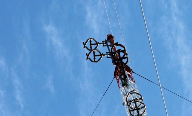
The use of a multi-bay antenna has the effect of focusing the RF radiation outward, perpendicular to the element stack, thus limiting the radiation directly up or down from the antenna. This is more pronounced with one half wave spaced antennas, which may be an environmental consideration in heavily populated areas.
Thus, the best coefficient of zorch for an LPFM station would be a circularly polarized, 1/2 wave spaced, 2 bay antenna. This antenna would have some gain over a single bay antenna, take up less room on a tower than a full wave spaced antenna, offer good RF protection performance for the general public living and working under the antenna, reduce wasted upward radiation and offer good building penetration for the ERP. It would require a slightly larger transmitter and more electricity, but that trade off is well worth the effort.


I’ve seen a similar effect on the 440 amateur band. I’ve got a repeater with a 10dB gain up 1100 ft ASL (400 ft AGL), yet the coverage under it (within a few miles) is horrible. The antenna gets that gain by focusing the signal horizontally, leaving very little above and below that line. If I ever have to replace that antenna, I’m going with a 4-bay loop antenna that will have less gain but much better coverage below the antenna.
I suspect the FM station whose antenna is 200 ft higher suffers a similar problem with their 4-bay antenna as the signal skips over the nearby listeners.
Bob M.
Speaking of zorch, I just replaced a shorted diode and two blown-up 100uF 63V capacitors on an electric gate control board due to a nearby strike.
This same strike caused an Astron RS-35M power supply to crowbar; after cycling the power it worked fine.
This zorching also took out the diodes (and one foil feeding them) in an attached RF remote receiver board. I fixed it twice (the other foil burnt up the second time) with new diodes but the third time it couldn’t burn anything up so it just destroyed the rest of the board.
I think it’s time for some MOVs.
Bob M.
I’ve read this post many times, with great interest. One thing you didn’t mention, though, is how you derived your coefficient of zorch. Empirical evidence? Laboratory experiments? I’ve had a couple of 2 bay 1/2 wave CP translators that did really well for their power.
Joel, This is based on my own experience over the years. Lower powered FM signals benefit from more TPO, even though the antenna ERP remains the same across various models. I have not actually studied the math on this, but several antenna engineers say it makes no difference. Yet my experience (and yours) say it does. The actual number is a percentage of perfect, e.g. 1.00 being a perfect antenna, everything else is something less and were picked arbitrarily by me.
Paul, thank you again for this article, I have reviewed it periodically as I make a decision regarding a potential LPFM, and the time to decide about which antenna type is getting closer.
I am applying to maximize HAAT at a different antenna location than my current CP allows.
Any other words of wisdom or revisions in your “coefficient of zorch”? For my particular application, I will be fighting significant distant co-channel interference from two directions. It seems like your original recommendations would stand in that situation. At the new site, tower room will not be a factor so I will prefer a 2 bay option. At my original location, I was considering a simple one bay CP as I would not have much room on a (much shorter) mast.
BJ, obviously cost is also a consideration. Based on what you have said, I would be careful going very high with flea power. Yes, FM is line of sight, however, there is also a signal density characteristic which is particularly important with co-channel interference. My recommendation would be to try and stay above 75 watts ERP regardless of the type antenna. With a two bay 1/2 wave spaced antenna, your transmitter power output will be more than your ERP, which is okay. With co-channel interference, the most dense signal will be the one demodulated. I would also consider mono instead of stereo.
Thank you Paul,
Yes, I intend to stay at 100w ERP. And I also intend to test in both mono and stereo, since our format will likely be at least 50% talk anyway.
Cost is a consideration but it’s essentially a one time investment. Unless the budget gets really tight, I’m going to prefer the two bay option.
It seems I may not want an antenna gain of unity, necessarily? Not being a technical person, I’m amazed at the variety of two bay options, with gains anywhere from the .7 you quoted to. Close to unity.
Well a year later! We ended up at our original tower site (no rent, but not very high neither – HAAT barely 12m). We have a two bay 1/2 wave spaced CP antenna. Co-channel interference limits coverage area to 1-1.5 miles in most directions (urban area for the most part). I am praying either to move to a different channel (not many available) then go higher even at a different site eventually.
Amateur hour alert… Is there any reason to consider a 1/4 wave spaced two bay? I’m trying to maximize the radiation center height on our puny mast… What would its Zorch look like?
Another (late) update: nine months ago we were able to switch frequencies, to a channel with much less co-channel interference. That, of course, helped our coverage a lot, up to 2-2.5 miles around with good coverage. Then three months ago, one of our co-channel interferers went off the air, so a little bit more help to the north in terms of reception quality. Still looking to increase height, either at our current site (though municipal codes are a barrier), or the miracle of a low cost 150′ tower (just kidding).
keep in mind that antenna gain really starts to show up out at the far end of radio-line-of-sight “LOS” ( think 20 or 30 miles )
for the LPFM station the on channel ( co-channel ) and god forbid adjacent channel HD jamming signals are going to overcome your signal long
before your antenna disappears from radio line of sight.
You will need a 10 to 1 power level to overcome the HD jamming signal as it acts
like a AM signal distorting your audio in a way the old FM receivers didn’t expect…
you do not get the 3 to 1 FM vs FM advantage.
So getting your antenna as high as you can in the primary factor with the secondary goal of enough power to penetrate buildings.
So TPO or power at the antenna should be kept above 50 watts and a 1 bay or 2 bay circular half wave spaced antenna seem to work the best.
if the 1 bay can be supported higher then it may work better then the 2 bay that is a little lower….
remember its radiation center is from the mid point between the bays.
cost is also a factor for small lpfm stations the one bay antenna cost less
and is far easier to get installed on a low cost push up TV mast.
it’s also hard to keep the guy wires clear of the 2 bays on a push up mast.
bottom line the gain of the antenna will not make any difference with in our 1 to 3 mile good signal area.
if the fcc paper gain is low as on the half wave spacing models
and your math gets a little more transmitter power output on the license that will help..
Ideal set up would be ~150 feet high and one bay in the middle of town , if you are on the edge or town then the 2 bay might be better if you can point it towards town.
Brad, this is very late acknowledgment of your followup, thank you. I read this post, still, every so often, to refresh my memory – you know compared to everyone else here I am an amateur. This time – I was sparked because I’ve seen a few LPFM apps with 2 bay, 3/4 wave spacing, and was wondering why. My guess would be lower TPO. Since antenna gain isn’t a factor, we’ll probably keep where we are. Oh, and since my last post we were able to increase HAAT from a measly 12m to almost 22m so that has helped a little bit too!