Amplitude Modulation (AKA AM) was the first modulation type to impress audio on an RF carrier. Prior to this, information was transmitted via on/off keying of a continuous wave transmitter using Morse code or some equivalent.
There are several methods for generating AM in a transmitter.
1. Low-level modulation. The modulation is developed in the first stage RF section, then amplified by subsequent stages to full power. Simple and easy to implement, especially for mobile transmitters and SSB installations. Disadvantages come from the need for linear amplification through all the stages requiring class A or AB amplifiers and do not reproduce wide band AM well.
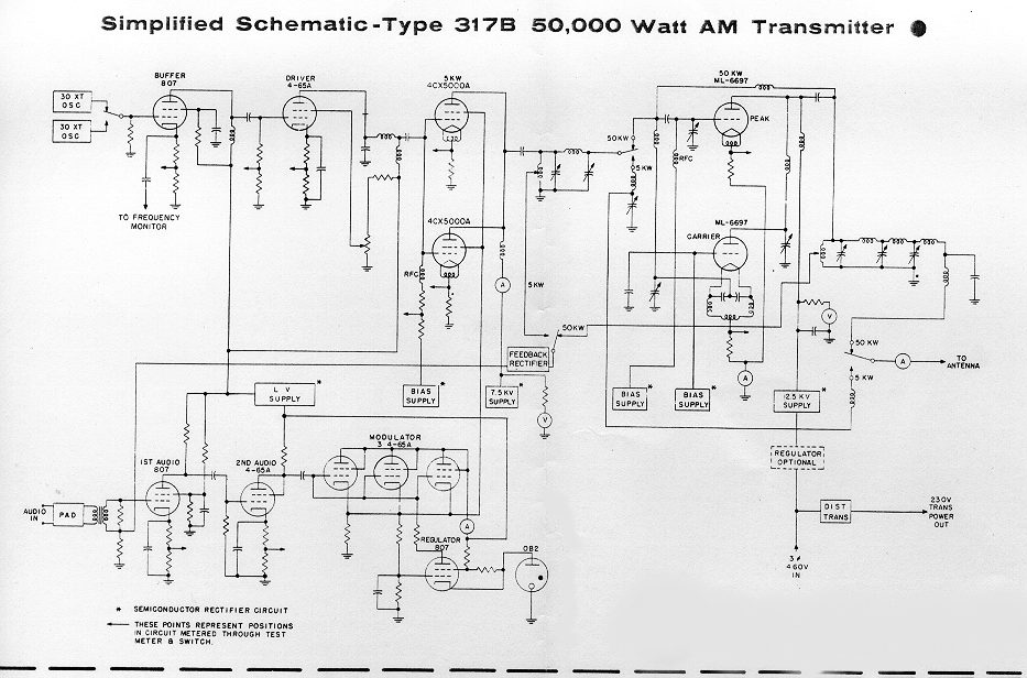
2. Doherty modulation. William Doherty came up with an ingenious way to use a low-level linear modulator with good to excellent efficiency. Under full carrier, no modulation conditions, the carrier tube is generating the RF carrier, and the peak tube is mostly cut off (very little current). When modulation is applied, the peak tube then begins to conduct, the output of this tube is combined with the output of the carrier tube through a 90° LC network, which is the same as a 1/4 wavelength transmission line. The effect of this is to lower the output impedance, thus allowing the carrier tube to modulate 100 percent.
Later, Continental Electronics and Jim Weldon somewhat modified this system in their 317C series high-power transmitters.
3. High level or plate modulation. The RF and Audio sections are developed separately within the transmitter, then combined in the final stage of the transmitter. Older systems used a modulation transformer. The advantages are all the amplifiers can be run class C or greater, which reduced electrical consumption and power supply requirements. Much higher power levels are achievable with this design. These transmitters also reproduce wide-band audio much better than low-level modulated units. They are also extremely rugged. Disadvantages are the system requires large audio sections and they take up a greater area and are not as efficient as later modulation methods.
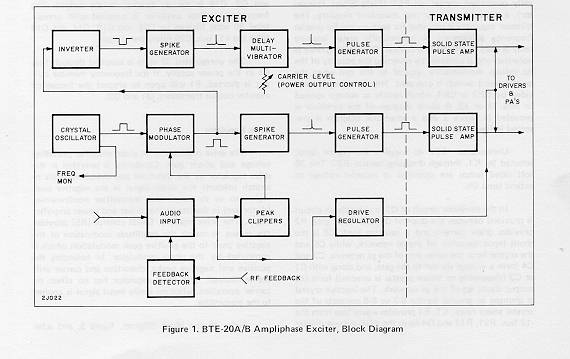
4. Ampliphase. A phase-modulated system developed by RCA where the transmitter developed two RF signals in the final, 135 degrees apart. To modulate the signal, the phase relationship between the carriers is varied, more toward 180 degrees would be a negative peak, and more toward 90 degrees a positive peak. These transmitters required less space and were more efficient than traditional plate-modulated transmitters. They required careful setup and tune-up to reduce distortion and somewhat unfairly earned the name “amplifuzz” from some engineers.
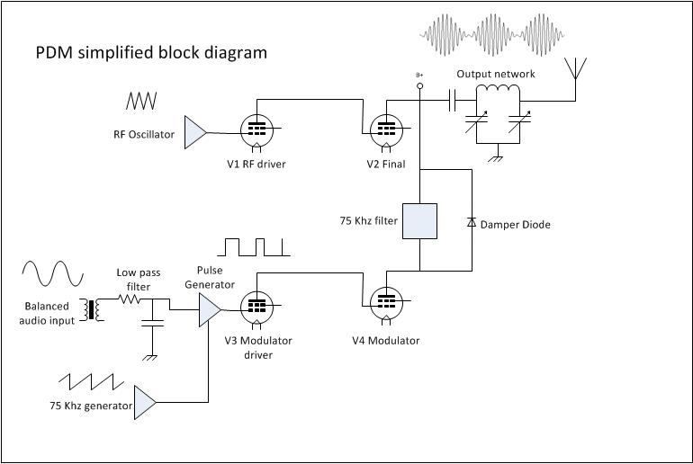
5. PDM or PWM. This is also a high-level modulation scheme but with some slight variations. The carrier power level and modulation levels are set by a PDM encoder card. In Harris transmitters, the PDM frequency was 75 KHz. The carrier is set by the amplitude of the PDM waveform, and the modulation is determined by the duration of the pulse. PDM transmitters require power supply voltages about twice the voltage of a standard high-level plate-modulated transmitter. They also require a damper diode to conduct the B+ voltage to back to the power supply during negative peaks, otherwise, the PA voltage will attempt to rise to infinity. I have found the damper diode to be the weak link in a tube-type PDM transmitter.
Solid state transmitters also use this design with either MOSFETs or BJT, which are then combined in parallel to generate the required output power. This is most often called “Class E” or something similar. In that system, each pair of modulator MOSFETs has its own fast-acting damper diode, usually protected by a fuse.
6. Direct Digital Synthesis. This is a patented design from Harris Broadcast used in their DX series transmitters. The incoming audio is sampled at either the carrier frequency or 1/2 the carrier frequency depending on where in the band the station falls. The solid-state PA modules are then switched on and off at the carrier frequency with the audio levels imposed on the carrier information. The explanation is simple, the application is complex:
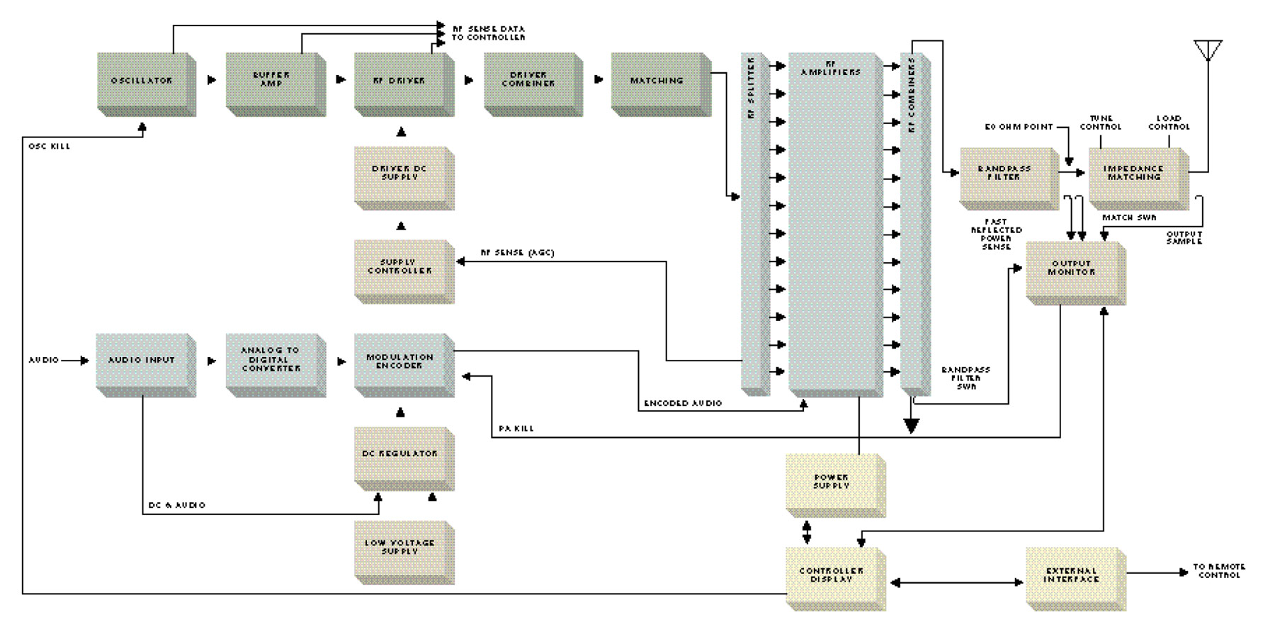
Of all these transmitters, the Harris DX series is the most efficient from a power input (AC) to power output (RF) perspective. There are several methods of reducing electrical use by reducing carrier power levels during lulls in modulation. The Continental 418E and later series transmitters can reduce carriers up to 6 dB using CCM. Harris and Nautel use similar systems on their DX and XL transmitters respectively. The wheatstone corporate blog has an article: Greener AM transmission Methods that details others.
As far as simplicity, serviceability, and rugged design, the high-level plate modulated transmitters cannot be beaten. Many Amateur Radio operators build these units from scratch using old parts, tubes, and other reused equipment readily available, often for free. I have, in fact, donated several 1 KW AM transmitters to ham radio operators over the years.
If I were to design a “transmitter of last resort,” to use in case everything else fails, it would look something like this:


The disadvantage of that design is it requires a 2KV power supply, which has its own set of safety concerns. I might substitute 833s for 813s and use heavier iron in the modulation transformer. That way the transmitter could develop a 500 to 1,000-watt carrier. The great thing about tube transmitters is, given the right output components, they can be tuned into almost any load. They are also easily adaptable for emergency operation into temporary antennas.


I also like 833A’s or 810’s. More driving power is required, but the performance without inverse feedback is very good. With 813’s, inverse feedback is a must for commercial broadcast to get the distortion down. In the above circuit, I would also take the DC final Plate Current out of the secondary of the modulation transformer, by adding a high inductance choke of at least 30 Henrys, with a blocking capacitor of at least 1 micro-farad to isolate the final Plate Current.
You are correct that there is no negative feedback in the above circuit, something that should really be included to keep distortion low. I may noddle around with this a little bit and come up with a better circuit, something like a 500 watt bullet proof transmitter, tunable from 540-1700 KHz. The tunable part may be difficult, but it would be a fun project.
With triode modulator tubes, you can get away without inverse feedback. My first 750 watt homebrew AM transmitter used an 833A in the final, modulated by a pair of 810’s which were driven by a pair of 807’s in “special triode connection”. No inverse feedback was used and the rig got me many compliments as to audio quality on the air. The Gates BC1E (1946) did not have inverse feedback and sounded good also. My BC-610F uses Eimac 100TH triodes as modulators without inverse feedback and it sounds good also. It is the tetrode and pentode audio power amplifiers that really require it because of secondary emission. Without inverse feedback on transmitters using these high sensitivity tubes, the old FCC specifications on harmonic distortion could hardly be met.
As to getting a broadband power amplifier without spurious emission over that large a frequency spread in the medium wave spectrum is probably a noteworthy challenge at this state of the art. But then again, who cares about spurious emission these days; we have IBOC!
Suppressing 2nd and 3rd harmonics is an issue. It might be handled this way, split the band in half (540-1000 KHz and 1010-1700 KHz) and design low pass filters for each part of the band. This would mean, however, that the antenna impedance would have to match the filter’s.
I seem to have missed anything about generation of Amplitude modulated waves via a switch modulator, Can someone explain how this happens.
No links, need a personal explanation
Un radioaficionado de argentina LU5EPH es la primera persona en modular un equipo a valvulas modulado por pantalla lo que siempre se llamo vajo nivel, el dice haber logrado alto nivel al modular las pantallas por ancho de pulsos osea pwm! eso se le escapo a harris y demas companias!!Una ves mas los radioaficionados demuestran ser grandes experimentadores!Se lo escucha muy bien desde chile en 40m!
Have thought about AMing a GE Mastr II LMR radio for use on the 6m ham band (running a dual mode AM/FM rptr with a rcvr somehow auto decoding AM or FM using an audio voter and then modulating the transmitter with both). I have looked at using a conventional high level modulator in series with the DC feed to the PA and driver of the Mastr II but I would have to reduce voltage in the feed to prevent the AM peaks from blowing the 12V rated xstrs OR sub 28 or higher voltage xstrs for the 12V ones which would lower the carrier output)…anyone else have a better idea?? I dont want to take an old AM xmtr and FM it too (which would be easier to do but then the quality of a GE xmtr would be lost and a lot of the older AM 6m xmtrs did not like the duty cycle needed in rptr service. (WHY dual mode? well, AM is a weak signal mode so the rptr in AM transmit (and possibly AM rcv) could have better usable range than a FM only rptr and the dual mode means local FMers could talk to AMers at longer ranges…at least it would seem to work that way…its just something I want to play with
Also I might add I considered Class E but in my research, Class E looks to require an isolated “ground” on the audio section…something I want to avoid… 🙂
There seems to be some ‘confusion’ re Class E.
PWM most definately uses Class D, i.e a pure switch and your just changing the duty cycle of a square wave at an audio rate and then running this thru’ an LPF to remove the switching frequency to provide D.C. (moving at an audio rate). Simplicity itself! I think that explains the Switch(ing) Modulator also?
Class E is does not need an isolated ground!
Its just another switching amplifier (R.F. ONLY?)and needs to run into a reactive load.
Respected
I own tube RS 3005CL and I would like to do AM modulation of the first linear or grid.
Do you have a service manual for this pipe or a better proposal
thank you
Just what I was looking for- a simple summary of the different common way to modulate AM. Thanks. I like your style of technical writing. Hope I can find more from you.
73
GregTheHam
I am in the process and have had some good success, of building a grounded grid (GG) amplifier and plate modulating it. It seems to work OK and runs a 3-400Z plate modulated by a pair of 3-400Z in class-B. The 3-400Z RF tube is biased at -90 volts for class-C as Eimac suggests. Although it seems to work quite well, I get good reports of a quite and strong carrier and good modulation, it has the strange characteristics of the grid current and the plate current and the average RF output, modulating downward under voice modulation. Looking at the modulated RF output on an oscilloscope, it looks good. I am just puzzled by the grid, plate and RF output modulating downward. Any thoughts or suggestions? 73 WA4QGA
By “modulating downward,” I think this might be carrier shift from a poorly regulated power supply. 100% positive modulation is 4 times the carrier power, which can put a serious strain on any power supply.
My power supplies are stable. They are separate for the RF deck and the modulator and both have large choke input PS. I have measured them. Modulating with a 1KHz tone shows positive increase in RF current, something like 3.3 to 3.5A into a dummy load (544W to 612 watts). People tell me it sounds great. have just made myself kind of neurotic with the actions of the grid and plate current under modulation. I had the idea everything would “kick” upward. That may not be the characteristics of a GG amplifier being plate modulated. I don’t know… I have tried switching the polarity of the mic with a XLR polarity changer. Back in the old-days, it seemed to make a difference with the D-104 mics. Thanks for your reply. 73 WA4QGA. You can see a lot of what I build on my QRZ page and YouTube channel, ElPasoTubeAmps.