To any who lives in the capital region, the WGY tower near the intersection of I-90 and I-88 in the town of Rotterdam is a familiar site. It is big, tall, and conspicuously marked with a huge “81 WGY” on the southwest face of the tower. At night the call letters used to be lit up by a spotlight but that may have been turned off in recent years.
In my time as chief engineer there, I found several file folders of memos and other materials about the building of the tower, which started in 1936. Prior to that, WGY used a T-top wire antenna, first from the General Electric plant in Schenectady (1922-25) and then from the current tower site in Rotterdam. Located with WGY were GE’s experimental shortwave stations W2XAF and W2XAD.
When the station increased power to 50,000 watts in 1925, many reports of fading were received from locations 20-50 miles away. WGY engineers studied the situation by doing a full proof on the antenna. They found an elliptical-shaped pattern with nulls to the north and south. This coincided approximately with the T arms of the T top antenna, likely due to the self-resonating effect of the support towers for the ends of the T.
NBC, then owners of WJZ (now WABC) in NYC had studied this problem for years and came up with a new antenna design for Standard Broadcast, the uniform cross-section guyed tower. Starting in 1935, WGY began to investigate installing such a tower in South Schenectady, as the transmitter site was then known. One report showed an efficiency gain of 430% over the T top antenna that was in use. The General Electric construction and engineering department raised several objects to the standard triangular tower then and now commonly used for AM radiators.
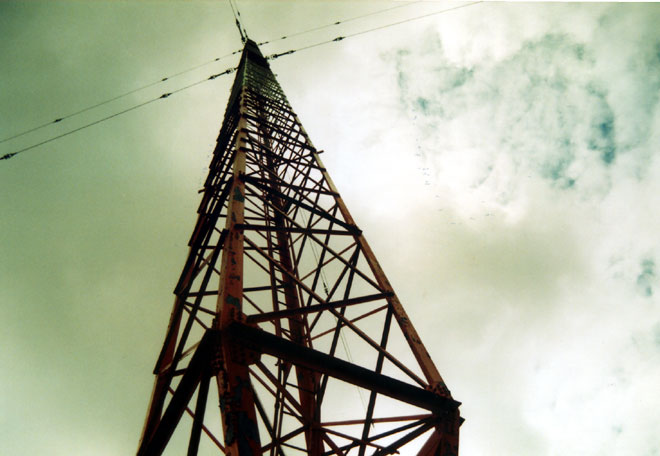
Much mechanical planning and effort went into the design of the tower, which is a square tower, a 9-foot face, 625 feet tall. During the planning phase, KDKA was installing a similar tower, which collapsed when it was being erected in 1936. An analysis of the failure showed that one of the guy anchor cable sockets pulled out of the concrete (which was improperly poured). This may also be the reason why the KDKA tower collapsed in 2003, although I never read the engineering report on that failure. Nevertheless, GE Engineering felt that forging the members of a triangular tower weakens them and was too risky, thus, a square tower was the solution.
Further, every component of the tower was tested individually. Often, two of a type were build, with one being tested to destruction. Two base insulators were made for this specific tower. The first was tested to destruction at the National Standards and Institutes laboratory in Washington DC. It was found that the insulator withstood slightly more than 1,200,000 pounds of pressure. The working load (tower dead weight) of the base insulator is calculated to be about 430,000 pounds, thus almost a 3:1 safety margin.
The wire rope used for the guy wires was also tested to destruction. The working load on the upper guy is about 24,000 pounds, the wire rope broke at nearly 120,000 pounds. The concrete, guy anchor sockets, T bars, and all other parts were likewise tested.
Electrically, the tower is 186 degrees (it was 180 degrees on 790 kHz, the former WGY frequency). It had a 40 X 40 foot ground mat with 120 buried ground radials. The ground radials were #4 hard drawn stranded copper. When we investigated the system in 1999, it was complete and unbroken. The radials, ground screen, strap and all other metal component showed no signs of deterioration. It helps that the soil surrounding the tower is a sandy loam and well drained.
The tower was fed with 600 ohm open transmission line, 180 degrees long. Initially, the system had been designed for high power operation up to 500 KW. However, when the transmitter was replaced in 1980, a new Harris ATU was installed, which can only handle 50 KW. I recall the base resistance to be 192 ohms with -j85 reactance.
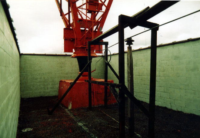
A concrete wall surrounds the base insulator. This was installed in early 1942 to prevent the base insulator from being shot out by sabbators during WWII.
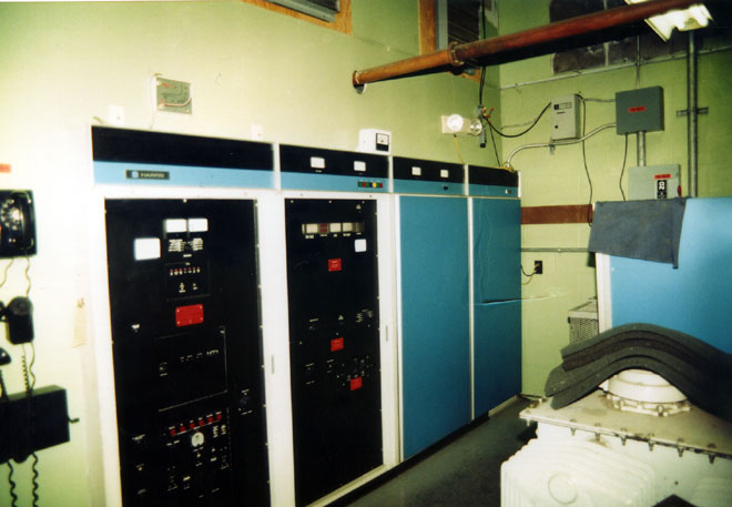
When I worked there, the station had a Harris MW-50B transmitter. This unit was in slightly better shape than its counterpart at WPTR across town. I did find some of the same quirky things with it, however. Our consulting engineer had a good line, “Harris, where no economy is spared…”
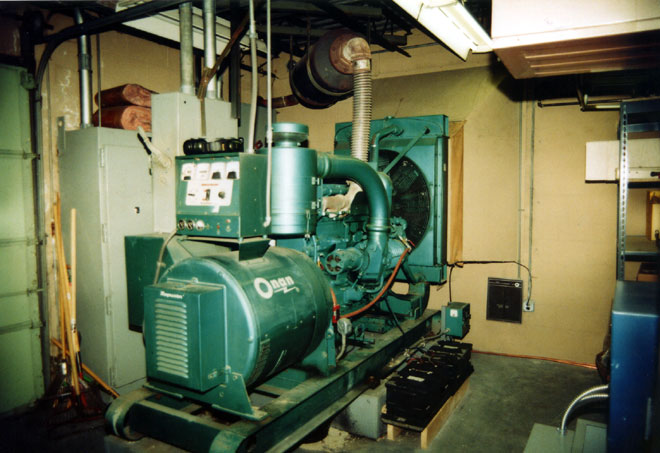
The site had a FEMA owned backup generator installed in the 60’s. This was an Onan 225 KW diesel powered unit. 225KW is likely a conservative estimate as those units were way overbuilt. The original fuel tank was buried out behind the building. FEMA contracted for it’s removal in 1995 because of concerns of leaks and soil contamination. When they dug it up, the primer was still on the tank. After getting the tank out of the ground, the contractor cut a large hole in it and lowered a person into the tank to clean it out. Something that should be profiled on the Dirties Jobs TV show.
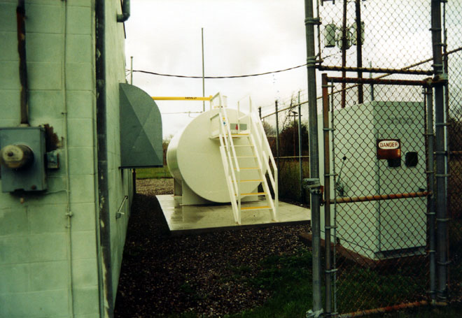
The new tank was installed in the old outdoor transformer vault. It is a 5000 gallon double walled above ground tank with monitoring system.
It has been several years since I have been to this site. I know they installed a Harris DX-50 sometime in 2001 or so. They also may have replaced the open transmission line. WGY now transmits in HD radio, which they are able to do because the tower was well designed and installed.

For some reason WGY never had an extremely strong nighttime signal out here in Wisconsin. KDKA and WABC always did better. I have a QSL card from WGY dated in 1961 which didn’t answer any of my questions asked in my verification letter. The only thing it mentioned was a “50 kW GE transmitter” and “One 625 foot tower”. The QSL card was a rather drab orange color with small black print. I always wondered if they were using a BT-25A at the time or a 4BT50A later model. The station was owned by GE at the time.
John, as far as I know, WGY had a BTA25A that was one serial number lower than WPTR. I could not find any pictures to confirm this, nor any maintenance records. WTPR’s transmitter was serial number RD-4 and it was made in Syracuse.
Interestingly, the WGY transmitter site also once had a railroad siding. The old transmitter building was to the east of the current building. It housed all of the experimental GE stations (shortwave, VHF), plus a police transmitter on 1660 khz. They must have felt moving all that heavy iron justified a siding.
When I was CE, we didn’t have money for QSL cards so I had a letter that I sent out. I sent out many of them as I recall.
Paul: Maybe in some future edition of this blog you could do a write up on the Continental 317C series Xmtr. Like to see what you have to say about them. WOR 710 KHz NY.City had a pair of em as I recall.
Looks like there is an old magneto telephone set on the wall next to the transmitter…..what did this connect to?
@Jim, that telephone goes to the ATU building at the base of the tower
Thanks Paul…did I see your name associated with the WINE/WRKI move recently? Along with Pat C., I did the original installation of the Harris AM & FM transmitters there.
Jim, we did indeed do that work
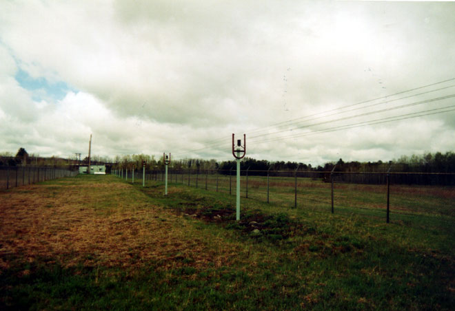
I know this post is over a year old, but the more I look at the transmission line in the third photo, the more I’m thinking it’s what RCA touted as “five-wire line” (counting the inner two as one) shortly before WW II, unbalanced transmission line in the form of skeletonized coax with the four outer wires all grounded (by that U-shaped support) and the inner two wired in parallel as the “hot” side. It was supposed to be a lot more stable than two-wire line and simpler to couple to the ATU.
Not sure what the typical Z of the line was — 600 Ohms seems high but it was higher than modern 50 or 75 Ohm stuff. If I can find the old RCA Broadcast News article, I’ll quote it or link to it.
Some of the superpower stations in Europe and Asia still use a scaled-up version of this method.
I’m pretty sure this is the cite: Brown, G. H., Characteristics of Overhead Unbalanced Transmission Lines, Broadcast News (RCA), May, 1941. Not sure where my copy has got to.
When I first saw it, I thought it might be 450 ohm impedance. I did find the GE engineering department study, which stated “600 ohm concentric transmission line” and the matching network component values agree with this statement. Somewhere in my history file I have a copy of that paper. I believe this line was installed in 1939 and is still in use today.
As of 2010, they were using a 3DX50 as the main, and the Harris remains as a backup.
When I was on the property, also in 2010, the open transmission line was still going out to the tower too.
If it works, and works good, why mess with it?
TO WHOM IT MAY CONCERN,
MY GRANDMOTHER ; HELEN KROSS HESELTINE, SANG ON WGY MANY MANY MANY YEARS AGO; IM GUESSING;20’S-30’S. I WONDER IF THERE IS ANY INFORMATION AS TO WHEN SHE SANG ON THE STATION. I REALIZE ITS A LONG SHOT, BUT MAYBE THERES A SAMPLE OR SOME KIND OF RECORD / DOCUMENT; SHE LIVED IN SCANECTADY, 1028 STATE STREE. PLEASE LET ME KNOW IF THERE IS ANY RECORD OR INFO ON THIS MATTER. THANK YOU SO MUCH,
GEOFF BELL
GRANDSON OF HELEN KROSS HESELTINE.
THANKS, GEOFF! YOU MAY WANT TO CHECK WITH THE SCHENECTADY COUNTY HISTORICAL SOCIETY! THEY MIGHT HAVE SOME INFORMATION ABOUT IT!
If the feedline is 600 ohms and the DX is designed to work into 50 how is the 12:1 mismatch tuned?
As I understand it, the problem with the open wire line is that the solid state rigs trip off when birds and other animals get caught in it. The tube rigs would crank on. I am told WSM went to buried heliax because the (then new) DX50 kept tripping off and someone would have to go out to the tx site and clear off the line.
Rob, there is a matching network in the transmitter building that matches the 600 ohm line to the 50 ohm transmitter. While I was there, we never had a problem with birds or animals getting into the open transmission line.
This is wonderfully informative ! Thank you ! It is my understanding that my great-grandfather P W Jensen was the on-site foreman on the construction of the WGY tower project. I would love to know of or see any possible surviving documentation of any kind relating to the construction of the original tower – thank you !!! – KJ
I respectfully disagree that WGY has a poor signal in Wisconsin – my grandmother in Lake Geneva loved WGY – I listened with her to WGY, KOA, KSL, WHAM and many other stations – WGY had at least an armchair S9+ dB signal in her part of the Dairy State!
Books about Broadcasting History (including WGY, WGFM, WRGB, and the General Electric Shortwave Stations) that I wrote under my Pen Name “Wilbur Hay” that you might be interested in purchasing copies of, and reading:
https://www.barnesandnoble.com/w/real-life-television-and-radio-stations-and-defunct-group-ownership-companies-that-are-the-inspiration-for-the-npvt-stns-matthew-parij/1144940490?ean=9785883592798
https://www.barnesandnoble.com/w/additional-radio-and-television-stations-that-are-the-inspiration-for-the-npvt-stations-matthew-parij/1145011511?ean=9783043732923