We have a Harris Z5-CD transmitter for one of our FM stations. Brand H is not my preferred make, however, it was already installed when we bought the station, so I have to live with it.
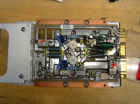
This particular site gets hit by lightning strikes often. Normally, it does not affect anything until the transmitter gets turned off for maintenance. Then, almost invariably, when turning the transmitter back on one of the modules will fail. Most often this is manifest when one of the two power supplies shut down causing the transmitter to run no more than 20% power.
The way this is troubleshot is to slide each module out and turn the transmitter back on. When the power supply stays on, the bad module has been located. A confirmation test is to check the MOSFET for a short circuit between Drain and Source. This short circuit condition puts a direct short on the power supply causing it to crowbar and turn off.
So, once the bad module has been located, and the spare module is installed in the transmitter, then what? Most engineers call Harris and ship the module back for repair. Most engineers don’t want to mess with unsoldering a surface mount MOSFET and soldering a new one in. I find it moderately entertaining to fix things myself, so I do not do what most engineers do.
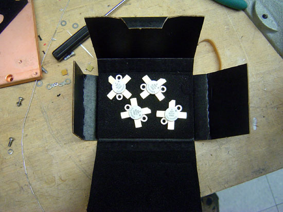
The MOSFET in this particular module is the BLF177, made by NXP. Harris will sell you one for quite a bit of money. You can also buy one from Mouser for about half the cost.
Once the parts are obtained, the worst part of the entire job is unsoldering the old MOSFET. This takes some patience and skill. What I found works best is to melt some solder on the foil leads and get them good and hot. Since this MOSFET is already destroyed, we don’t have to worry about heat, etc. The one thing you do not want to do it actually break the MOSFET open. That is because it contains beryllium oxide, a known carcinogen. Once all the solder is liquid, carefully pry the foil up with a small screwdriver. There are several components that have to be moved to work on this.
After the old MOSFET is removed, clean up the solder pad with a solder pump and solder wick. I like to use a little liquid flux on the solder wick, it makes things go faster.
Once all the old solder is cleaned off the solder pads, I brush a light coat of liquid flux in the pad. Again, this makes things go faster.

The new MOSFETS are very sensitive to static discharge, so I always use a static drain wristband when handling them. I place both MOSFETs onto the circuit board. I then solder them on using as little heat as possible from the soldering iron. Again, the MOSFETs are sensitive to heat and one can easily be destroyed if it gets too hot.

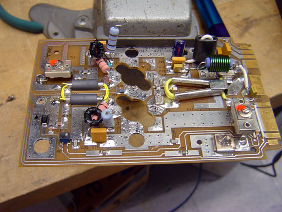
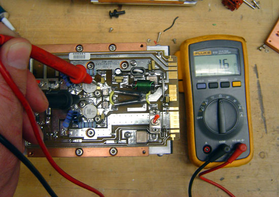
This is the module with the new MOSFETs soldered in. I use defluxing compound to remove all the extra flux. Once it cools off, I test the new module with a DVM:
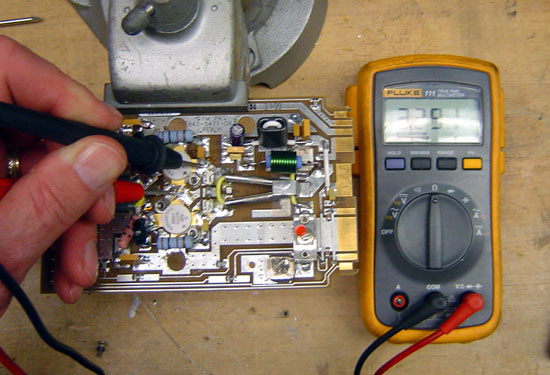
If the MOSFETS are good, they will have an internal resistance of around 3.3 MΩ. If the module is bad the MOSFETS will read only a few ohms if shorted:
That is how you do it. I think Harris charges $775.00 per module to repair. I fixed this one for $240.00, but that is not the reason I did it. I did it for the fun that was in it.