We have a Harris Z5-CD transmitter for one of our FM stations. Brand H is not my preferred make, however, it was already installed when we bought the station, so I have to live with it.
This particular site gets hit by lightning strikes often. Normally, it does not affect anything until the transmitter gets turned off for maintenance. Then, almost invariably, when turning the transmitter back on one of the modules will fail. Most often this is manifest when one of the two power supplies shut down causing the transmitter to run no more than 20% power.
The way this is troubleshot is to slide each module out and turn the transmitter back on. When the power supply stays on, the bad module has been located. A confirmation test is to check the MOSFET for a short circuit between Drain and Source. This short circuit condition puts a direct short on the power supply causing it to crowbar and turn off.
So, once the bad module has been located, and the spare module is installed in the transmitter, then what? Most engineers call Harris and ship the module back for repair. Most engineers don’t want to mess with unsoldering a surface mount MOSFET and soldering a new one in. I find it moderately entertaining to fix things myself, so I do not do what most engineers do.
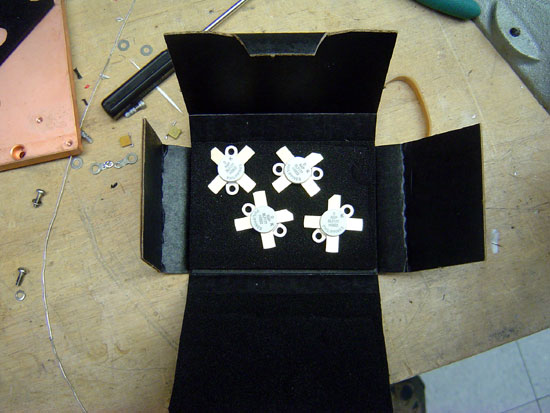
NXP BLF177 MOSFETS
The MOSFET in this particular module is the BLF177, made by NXP. Harris will sell you one for quite a bit of money. You can also buy one from Mouser for about half the cost.
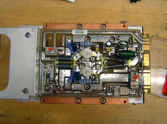
Harris FM Z series transmitter PA module with cover removed
Once the parts are obtained, the worst part of the entire job is unsoldering the old MOSFET. This takes some patience and skill. What I found works best is to melt some solder on the foil leads and get them good and hot. Since this MOSFET is already destroyed, we don’t have to worry about heat, etc. The one thing you do not want to do it actually break the MOSFET open. That is because it contains beryllium oxide, a known carcinogen. Once all the solder is liquid, carefully pry the foil up with a small screwdriver. There are several components that have to be moved to work on this.
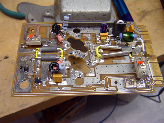
Harris Z series PA module with MOSFETS removed
After the old MOSFET is removed, clean up the solder pad with a solder pump and solder wick. I like to use a little liquid flux on the solder wick, it makes things go faster.
Once all the old solder is cleaned off the solder pads, I brush a light coat of liquid flux in the pad. Again, this makes things go faster.
Harris Z series FM transmitter module new MOSFETs waiting to be soldered
The new MOSFETS are very sensitive to static discharge, so I always use a static drain wristband when handling them. I place both MOSFETs onto the circuit board. I then solder them on using as little heat as possible from the soldering iron. Again, the MOSFETs are sensitive to heat and one can easily be destroyed if it gets too hot.
Harris Z FM series PA module repaired
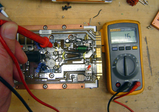
This is the module with the new MOSFETs soldered in. I use defluxing compound to remove all the extra flux. Once it cools off, I test the new module with a DVM:
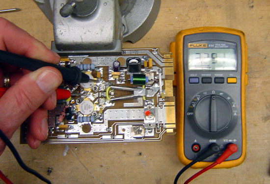
Harris Z series FM PA circuit board under test, resistance is 3.3 Mohm
If the MOSFETS are good, they will have an internal resistance of around 3.3 MΩ. If the module is bad the MOSFETS will read only a few ohms if shorted:
Harris Z series FM PA module under test, DVM reads 1.6 ohms
That is how you do it. I think Harris charges $775.00 per module to repair. I fixed this one for $240.00, but that is not the reason I did it. I did it for the fun that was in it.
EAS, or more properly, the Emergency Alert System, is a government-mandated system of encoders and decoders designed by the federal government to alert the public in case of war or other emergency. It and its predecessor, EBS (Emergency Broadcast System) have never been activated by the federal government. Both systems, however, are used extensively by local and state governments for things like weather alerts, amber alerts, etc.
Back in the mid-90s the FCC had a chance to redo the EBS and produce something that was a streamlined and effective tool for public warning. Unfortunately, the EAS system is neither. Rather, it is a cumbersome system of weekly and monthly tests scheduled around pre-conceived notions that how the system is tested every week will be how the system works in an emergency. In practice, this is generally a good theory of system design, but it has failed miserably with EAS. The reasons why are thus:
Most all emergencies are local or at most state-wide events. To this day, very few state and or local government emergency managers would be able to activate EAS for their area. The reason is there is minimal if any interface with the LP-1 EAS stations or station personnel. Ignorance and apathy on behalf of both radio station personnel and government officials is the main culprit.
Most stations are un-maned for large portions of the day. Even if government officials could/did call the station, chances are, nobody would be there. If by chance, arrangements were made to contact station employees at home, they would have to interface with the EAS equipment remotely, which adds complexity to an already complex system.
EAS messages are still mainly relayed from radio station to radio station, the so-called daisy chain network that has been shown numerous times to be unreliable.
The system of SAME codes, FIPS identifiers is not necessarily bad, the application in this case leaves something to be desired. The FCC had a chance to update EAS before the HDTV rollout. One would assume that any improvements could have been built into the new TV sets that are now being sold, but again, that opportunity was missed. For example, I suggested that each TV have a set-up screen option where the owner could input their zip code. They could also choose what types of alerts they would want to know about and even base the alerts types on the time of day. Live in a flood zone, the FFW (Flash Flood Warning) 24/7. Live in tornado alley, TOR (Tornado Warning), etc. The cable companies then pipe in the local NOAAall hazards radio station. All the sudden there is a real national alert system in place using mostly non-broadcast wireless systems. Add to that the ability to sign up for emergency e-mails and text messages for specific areas (many places are currently doing this) and there is multiple message paths.
The system as is not reliable and sooner or later that will be shown with a large-scale failure. Recently, the FCC held a summit with the Department of Homeland Security. The cliff notes version of this event is: Yes, the system can be made better. Let’s keep throwing the same ideas at the wall and see if anything sticks this time. Excuse me if I don’t do back flips, this is the same information that was discussed during the last “let’s revamp EAS” discussion back in 2005 (04-296).
In the meantime, the EAS continues to be a good fundraiser for the FCC enforcement bureau. Which, you know, it is easier to go to a licensed radio station and bust them for not re-transmitting the RMT (Required Monthly Test) than it is to go out and bust some of the numerous pirate radio operators, some of whom are operating in the same city/metropolitan area as a field office.
The shame of it is, it could work without a great deal of cost, very well.
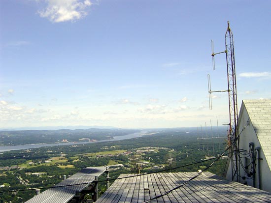
A few pictures from my last trip to one of our FM transmitter sites. This is a mountaintop site, in as much as a medium-sized hill is a mountain around here. This site has a 2.3-mile road through the woods that is almost impassable 3-4 months out of the year.
Previous engineers have walked up the hill with a toolbox. I can say this with all honesty; not me. In the past, they have also rented a helicopter, and used a snowcat, snowmobile, or an ATV with snow tracks. I’d do those things provided they are safe and insured. As I get older (and wiser), I realize that the only person who going to look after my well-being is me.
Anyway, the trip starts here, at the gate:
Gate to transmitter road
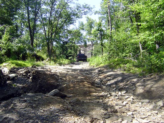
Then it goes up the hill:
Transmitter site access road
Some sections are worse than others:
washed out road
Along the way there are some nice views:
City reservoir near the transmitter site
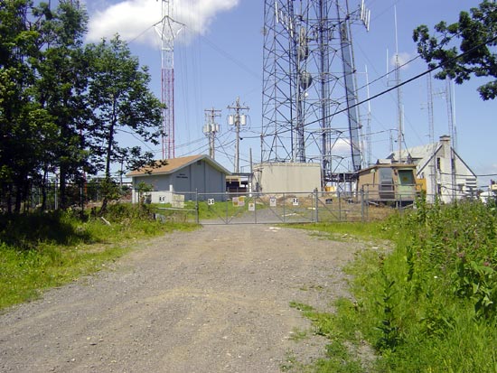
Finally, the gate to the tower farm:
Access gate to transmitter site
There are two digital TV stations, several cell phone carriers, some government two-way gear, some FM translators, Media Flow, and us at this site. There are also some Ham radio repeaters off to the side in another building. All in all, a pretty RF-intense site.
The view from the top:
view looking north
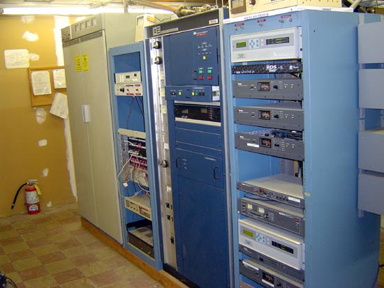
The reason why we came:
Transmitter room
That is a 24-year-old BE FM5B transmitter. The backup is a Gates FM5G, which aren’t we glad we have a solid reliable transmitter selection for such a remote site. Actually, we were supposed to put in a new Nautel V-10 here last year, but the money was spent on computers instead. Oh well, good thing there will be no computer crashes when we go off the air.
A standard maintenance trip consists of meter readings, comparing the reading to the last set of readings, changing the air filters, checking the remote control and calibrating it to the transmitter, checking the tower light sensor, etc.
Normally, the backup transmitter would run into the dummy load, but the backup transmitter no longer works. Parts are not available to fix it, so we operate without a net. One of the previous general managers asked if that keeps me awake at night, to which my answer was no, not at all.
Once upon a time, in the not-too-distant past, all long-distance communication in the US was handled by one company, AT&T. There was no other company that could transmit data over medium to long distances. The breadth and scope of their communications network are not understood by most people these days. Most people know that AT&T handled long-distance telephone calls for the Bell Telephone System until the Bell breakup in 1984. However, AT&T did a lot more than long-distance phone.
For example, if you watched the network news or network TV show anytime before 1980, it was likely brought to you via AT&T microwave system, known as AT&T long lines. Listen to the news on the radio, same deal. Before the widespread use of communication satellites and fiber optics, the AT&T microwave relay network was the only way to get various types of electronic media signals from one place to another.
Beginning in the late 1980s, competing local and long-distance telephone companies began installing fiber optic cables between company offices. That coupled with the increased use of satellite systems for mass media video and audio delivery services made the huge AT&T microwave network obsolete. Some of the old microwave sites that are located in downtown areas have been reused by local phone companies and cell phone providers. Many of the rural sites now sit empty.
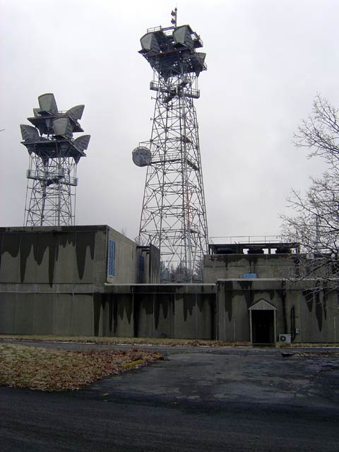
ATT long lines microwave site with towers
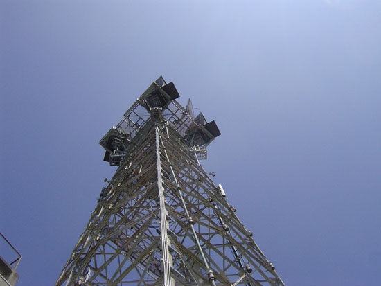
This is the former AT&T microwave relay site located near Kingston, NY. It is now owned by American Tower, Inc. There are two towers behind the building, only the tower on the right has a few active communications antennas on it. The taller tower is 190 feet tall and was built in 1957. The shorter tower is 120 feet tall and was built in 1961. Both towers and everything on them were made by Western Electric, the same company that manufactured the telephone sets. Chances are, Western Electric contracted the actual manufacture of equipment out to others, then billed AT&T, their parent company a markup. Something that would make all MBAs proud.
Western electric 190-foot tower, built in 1957
This tower was built in 1957. The structure and galvanizing are still in excellent condition.
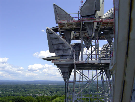
The large antennas you see on the towers are microwave horn antennas. They are no longer in use. Several transmitters and receivers would have been connected to each one of these antennas by use of RF multiplexers. Each microwave transmitter/receiver would have had several data channels. Generally, this was C Band microwave equipment, so it was in the 4, 6, and 8 GHz frequency range.
Western Electric KS-15676 microwave antenna
All of this telephone traffic was transmitted on digital data channels unencrypted. Many have argued that this allowed the government (most notably the NSA or National Security Agency) to intercept and listen to most domestic long-distance telephone calls within the US. There is a book called Puzzle palaceby James Bamford if you are interested in NSA history. It was written more than 20 years ago, so it doesn’t really apply today, but it is an interesting look at what the government was up to.
The building itself is huge, the first floor is 16,000+ square feet and the second floor is 10,000+ square feet. Only about 1000 square feet of this space is actively being used.
I believe this building was built in the late 1940s or early 1950s, just as Kingston was growing into a major IBM manufacturing site. It has remnants of the ATT coaxial-based system that was used prior to microwaves. The IBM buildings are located a few miles to the southeast of this location, they are another cold war relic for discussion later. The IBM buildings were a major computer research and development site in the 1950s until it closed in 1992. It was assumed that the Soviets had several spy satellites trying to steal secrets from the area, and the IBM facility was a primary nuclear target.
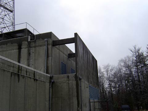
Blast baffle for generator cooling air intake
The microwave relay site has 12-inch re-enforced concrete walls. The ventilation air intakes have blast baffles to prevent a pressure wave (from a nuclear explosion) from blowing the ventilation equipment off of its mounts.
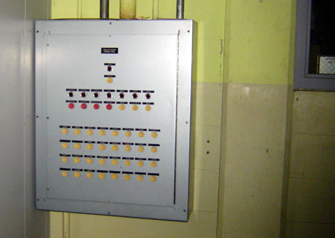
pneumatic actuator panel seals all outside openings with steel blast doors
All of the outside openings were able to be sealed with steal blast deflectors using a pneumatic control panel located in the control room. There was a five-minute timer, presumably to allow the HVAC units to be secured before the doors were closed. They were heavy gauge steel shutters designed to deflect the pressure wave of a nuclear explosion. Since this is an earlier building, it is likely that it is built to a 2 PSI pressure wave spec. Newer buildings were built to 20 or even 50 PSI. This microwave relay site would not have withstood a direct hit from a nuclear warhead, especially the higher-yield warheads that came later on.
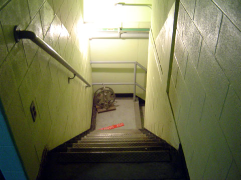
There is a bomb shelter in the basement. I found a couple of olive drab cans of civil defense water laying around. The lights were not working at the bottom of the stairs, so I chose not to go into the bomb shelter itself.
Stairs going down to the bomb shelter
“Okay everybody, the missiles are on their way, so let’s head down these stairs and pray”
There were two diesel generators, one was 325 KW which could run the entire building. The other was a 200 KW which could run the critical building functions. The fuel storage consisted of two 10,000-gallon tanks buried in the ground outside. Each steel fuel tank had a cathodic protection circuit. Basically, a small negative electrical current was passed to the steel tank to keep it from rusting. Apparently, it worked because when the tanks were removed in 2000 after 45 years in the ground, the primer was still on the outside of the tank.
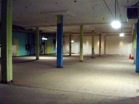
Frame room floor, equipment removed
On the main floor, there were rows and rows of wire terminal equipment, microwave transmitters, receivers, and data and RF multiplexers in racks. The room in the above picture is about 10,000 square feet, there is another 6,000 square feet beyond the plastic heat barrier. This microwave gear received and transmitted data from Albany and Germantown to the north; Poughkeepsie, Putnam Valley, Ellenville, and Spring Valley to the south. All of that equipment is gone now, replaced by empty space.
There are about 500 copper wire pairs of telephone cables that came into various parts of the building to carry the DS-1 and DS-3 circuits that interfaced with the TELCO office in Kingston.
All in all, this was a serious building, no expense was spared in the construction and equipment outfitting. The entire building is shielded with copper mesh screens embedded in the concrete walls. There were redundant systems on top of redundant systems, something that you do not see these days, even in government buildings such as emergency operation centers (EOCs) and 911 call centers.