The unitless coefficient of Zorch

Zorch is a term used to describe an over voltage or over current condition that usually leads to catastrophic failure, e.g. the power supply was zorched by lightning. There is also a quality to radio signals that defy and exceed theoretical definitions for service contours or power density.  That is quality defined as:

Zorch (adj): The ability of an RF signal to be received in unlikely locations; outside of predicted service contour, in steel structures, underground facilities, tunnels, etc.

It brings to mind the saying, “antennas are not amplifiers and amplifiers are not antennas.”
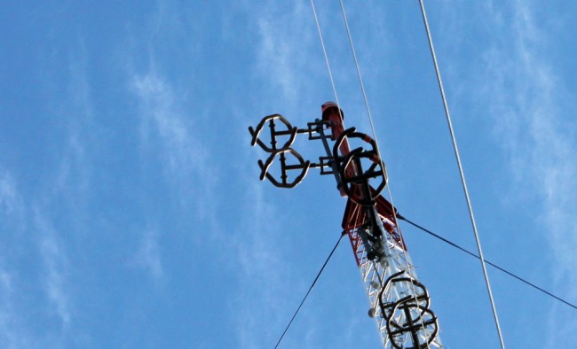
ERI circularly polarized 2 bay antenna

During the earlier stages of FM broadcasting, there was a notion that costs could be reduced by increasing antenna gain and reducing transmitter size. While theoretically, ERP (Effective Radiated Power) is ERP, broadcasters soon learned that high gain antenna, low TPO (Transmitter Power Output) installations lacked building penetration and had other reception issues.  Realizing that there is a trade off between antenna bays, transmitter power output especially in difficult reception areas, a great debate occurred and continues on what the optimal system is.  The answer is, it depends on the receiving environment.

Where this technical detail can be really important is with lower powered FM stations; Class A and LPFMs to be exact.  They are already battling against bigger stations that have tens or even hundreds of times  more power.  Certainly an LP-100 station has it’s work cut out for it.  The choice of antenna is perhaps one of the most important technical decisions to be made.  Choosing the right balance of antenna type, antenna gain, antenna height and transmitter power output can greatly influence reception reliability and thus coverage area.

A good study of this quality can be had by looking at various LPFM installations:

Station ERP (watts) Antenna Type Antenna Gain (power) TPO (watts)* Coefficient of Zorch
100 1 bay vertical 0.92 127 0.1
100 1 bay circular 0.46 253 0.4
100 2 bay vertical full 1.98 58 0.15
100 2 bay vertical half 1.40 83 0.2
100 2 bay circular full 0.99 118 0.5
100 2 bay circular half 0.70 166 0.7
100 3 bay circular full 1.52 77 0.46
100 3 bay circular half 1.01 115 0.52

*Includes 100 feet of 1/2 inch foam transmission line, Andrew LDF4-50A, loss of 0.661 dB  at 100 MHz, or 0.859 power gain.

Stations should try to get the transmitting antenna as high up as permitted without reducing ERP.  In other words, the FCC allows 100 watts ERP with 98 feet Height Above Average Terrain (HAAT) radiation center in their current LPFM rules.  Being lower in height will reduce the coverage area.  Going over 98 feet HAAT will cause the station’s power to be reduced, which will lower the coefficient of zorch accordingly.  Therefore, getting as close to 98 feet HAAT, which is different than 98 feet above ground level in many places, will net the best performance.

If a singular polarization (horizontal or vertical) is desired, vertical polarization should be chosen, as most mobile reception is by a vertical whip antenna.  For best reception performance, a circularly polarized antenna will work best, as receiver antenna orientation will not effect the signal reception.  A circularly polarized antenna has better building penetration and multi-path characteristics.  The FM broadcast circularly polarized antenna in not a true circularly polarized antenna, it is actually unpolarized.

The use of a multi-bay antenna has the effect of focusing the RF radiation outward, perpendicular to the element stack, thus limiting the radiation directly up or down from the antenna.  This is more pronounced with one half wave spaced antennas, which may be an environmental consideration in heavily populated areas.

Thus, the best coefficient of zorch for an LPFM station would be a circularly polarized, 1/2 wave spaced, 2 bay antenna.  This antenna would have some gain over a single bay antenna, take up less room on a tower than a full wave spaced antenna, offer good RF protection performance for the general public living and working under the antenna, reduce wasted upward radiation and offer good building penetration for the ERP.  It would require a slightly larger transmitter and more electricity, but that trade off is well worth the effort.

Orban Optimod 8000

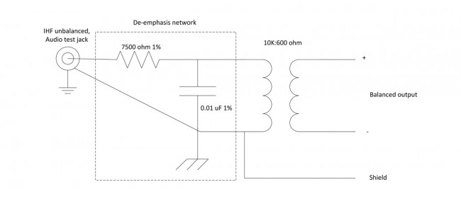
A piece of vintage gear from the late 1970’s, the Optimod 8000 was and still is a good sounding box.  I have often thought that these processors would make an excellent internet audio processor using the test jacks on the back of the unit.  The audio on these jacks is unbalanced and has 75 µS pre emphasis.   It would be easy enough to make a de-emphasis network and create balanced audio with a 10K:600 ohm transformer.  Some experimentation may be required with the transformer primary impedance value.  Orban notes that not less then 1 MΩ impedance should be connected to the test jacks.  For the internet station looking to copy the “FM radio” sound, this unit would do the job nicely.

The 75 µS  de-emphasis network would look something like this:

75 microsecond de-emphasis network, unbalanced to balaneced audio conversion
75 microsecond de-emphasis network, unbalanced to balanced audio conversion

In this case, the values for the de-emphasis network are fairly critical, therefore 1% or better tolerances for the resistors and capacitors is required.

Even better, an LPFM or some other radio station on a budget could acquire one of these for relatively little on eBay or somewhere else.  With a little TLC, most of these units can be rebuilt and put back into service.  I would recommend that some type of limiter be used in front of it, such as a Texar Audio Prism or CRL SEP-800.

Some classical music stations prefer these units.  I have noticed that they have a nice,  mellow, open sound.  Not at all fatiguing and yet still offer a nice easy 10 dB gain reduction.  There is also a modification that can slow down the release time on the gain reduction.  More gain reduction, AKA compression, can be had with something else in front of the unit.

The best part about these units, there is no rebooting, no processor lock ups, software glitches or any of that non-sense.  Additionally, a quick look at the front of the unit shows very few user controls, making it almost impossible to screw up and sound bad. They are well built and so long as the electrolytic capacitors are changed out, fairly bullet proof.  Other processors, not so much.

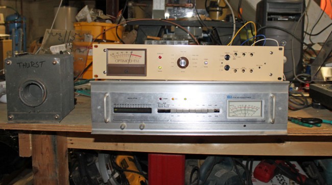
Optimod 8000A under test

This is an Optimod 8000A that I decided to put through its paces.

Really, how much more do you need?  I recorded this on the camera microphone using a replica table radio, seen near the end of the video on the right hand side of the frame.

I used the Technics SL-1200 MKII turntable through an ATI P100 turntable preamp into the Optimod.  The Optimod is feeding a BE FX-30 exciter running 15 watts into a dummy load.   The Optimod is running about 5-7 dB gain reduction, which is enough in my mind.  The BE FX-30 is still just about the best sounding analog exciter every made.

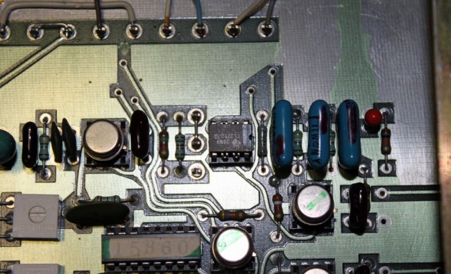
Rechipped Optimod 8000A, TL071 opamp

This unit has been re-capped and re-chipped at one point.  The re-chipping follows the Orban recommendation; the 4558 and 1556 opamps are replaced by TL071CP and TL072CP respectively, and the uA 709 and 301A opamps are left in the unit.  A good thing to remember, the uA709 and 301A opamps can be replaced by TLO71cP opamps in the event of failure.  The Texas Instruments TL0 series opamps are very good and readily available.

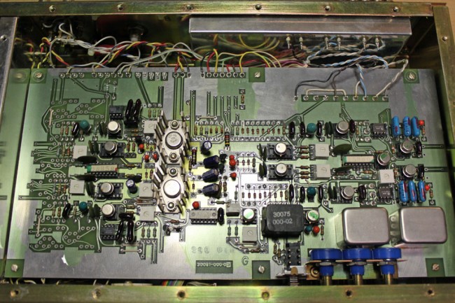
Optmod 8000A input and limiter board

Overall, this unit is in good condition, however, like many such units, it is missing its brown “Optimod” cover, which goes over the input/output controls.

Manual is available at the Orban ftp site: ftp.orban.com.

Chasing down a Pirate Radio station

I stumbled on this video on youtube. It seems like some old guy has too much time on his hands and is out being a private citizen vigilante:

Part one, he is driving around a neighborhood with a spectrum analyzer looking at signal strength:

Seems slightly creepy.

Then there is part II, the plot twist:

Actually, looks like a nice studio. PRE BMX II console, RE-20 microphones, and a live performance room at a radio station, what a concept.

Part III, the trouble of a technical nature sets in:

Brave man, fear of heights is overcome because of his love of radio. I myself suffer from Phronemophobia, not in myself, but in other people.

So this series goes on for some, then… First, a Notice Of Unauthorized Operation (NOUO), then, A construction permit for a C1 station! Wow!

So, they are currently building out their station and putting up a tower. Check out 89.1 Ken’s FM-KNNZ and see how they are doing.  The call sign is KNNZ, licensed to Hawley, MN.  Real radio, is alive and well in some places at least.

I wonder what kind of transmitter that is, I do not recognize it.

Good luck, guys.  I will have to check out the web stream, it sounds like fun.

FM Fool website

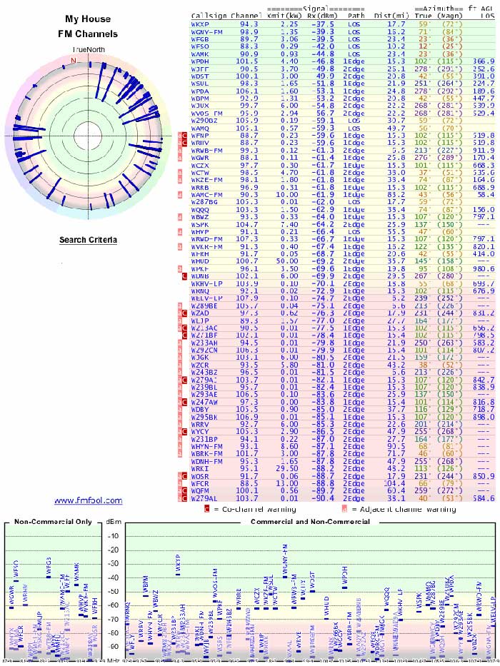
Just for geeks, the FM Fool website is.  Nonetheless, it is a cool site to look at and can be used as a tool to find out what stations are available in any certain area.  Using the FCC database and terrain profile, it will print out a radar plot of all signals for any address in the US:

FM Fool Radar plot
FM Fool Radar plot

This plot is for my house based on a 30-foot outdoor antenna and includes all FM stations that are even marginally receivable.  We kind of live off to the side of nowhere.

The transmitter database was last updated on July 5, 2012.  Longer bars represent stronger signals.  Details about each transmitter are provided in the table to the right of the plot.

This is a companion site for the TV Fool website.  If you want to see what off-air TV signals are available at any given location, this is the way to do it.  A few years ago, I was thinking of getting rid of the Cable TV in favor of off-air reception.  Unfortunately, there are only a few off-air TV channels available at my house.  Therefore,  I threw out the TV.  Problem solved.