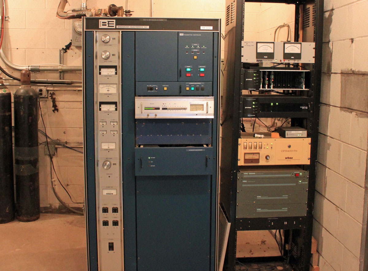
Not exactly sure how it happened, but one of our Nautel transmitters malfunctioned! It is a pretty rare event, so I thought the exclamation point was needed. One of the PA pallets went bad and the transmitter lost 1/2 a PA module. Since the TPO for this particular station is 7 KW, they remained on the air at full power. In the interest of staying on top of things, we fixed it anyway.
Diagnostics were simple:
- Fault lights on the front of the transmitter observed
- Press the status button to find out faults, which were Module D failed
- To to module sub-menu, find Module D and discover Q1 disabled, and Q3 shutdown.
- The problem is with Q3, order a new pallet from the manufacture
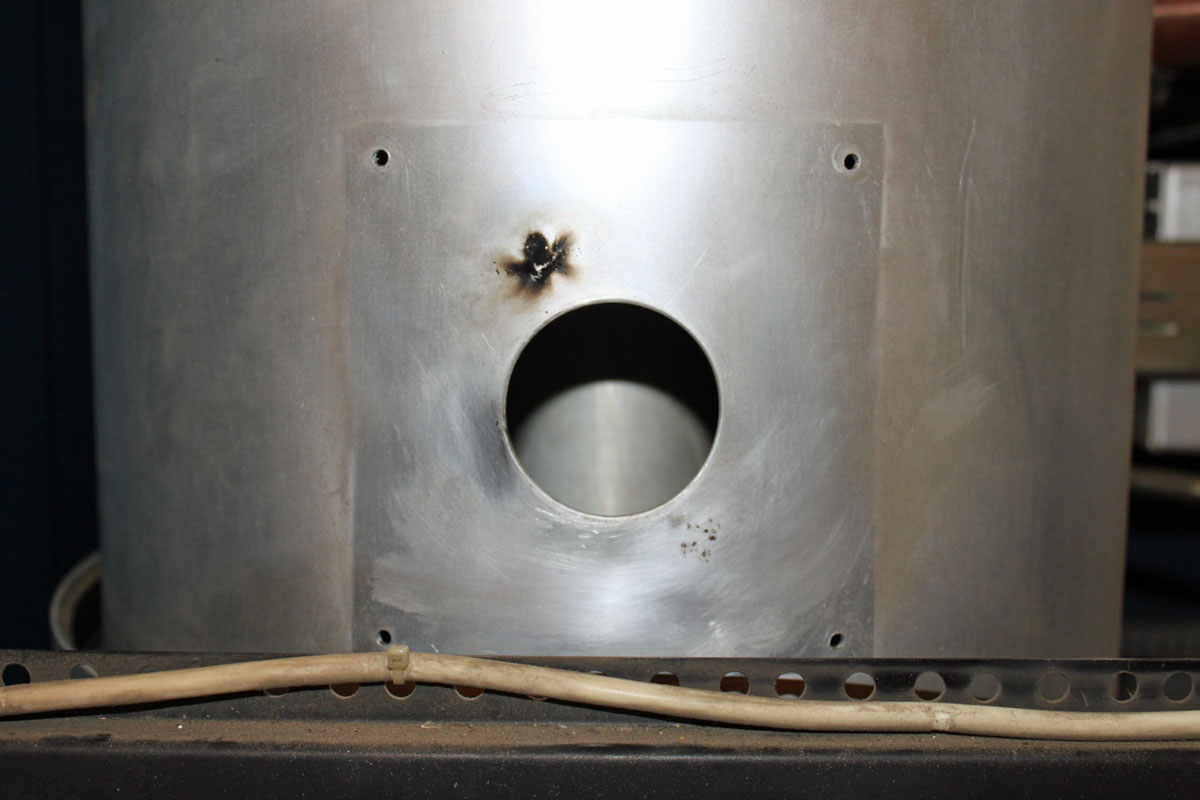
Upon removing the module, I did not see the damage at first:
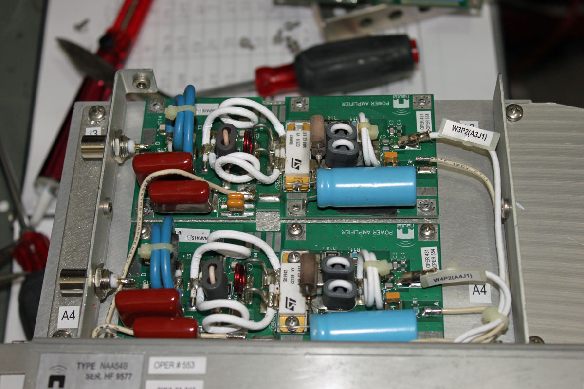
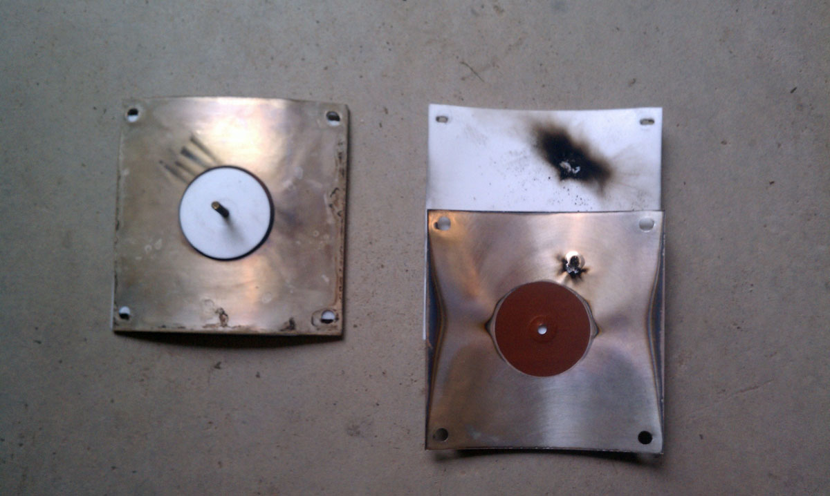
It is board A3, which for this particular flavor transmitter is a Nautel Part number NAPA16-B. Once I replaced the defective module with a new one, I discovered what looks like a symptom of the greater problem:
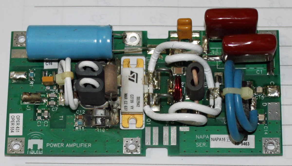
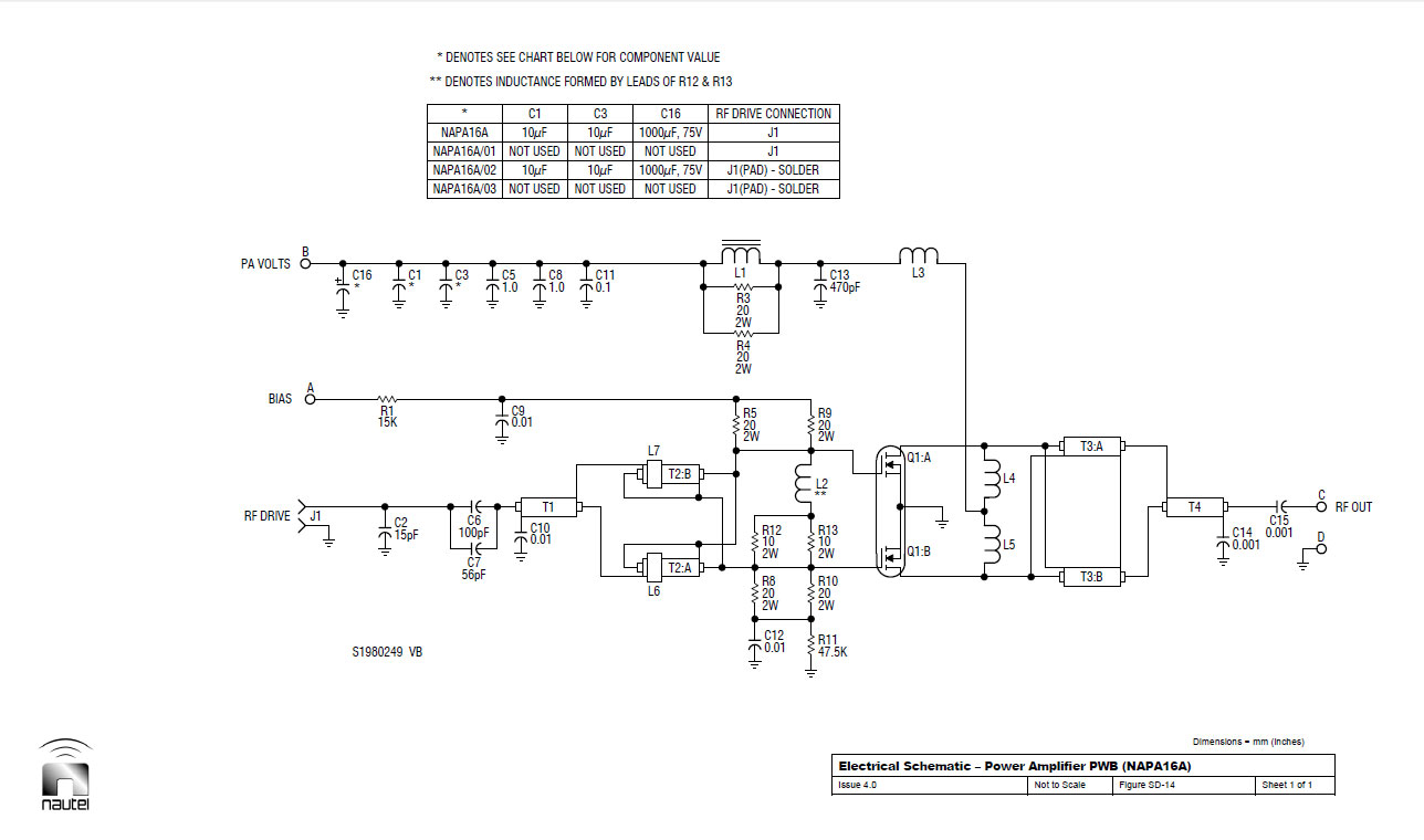
Over to the left-middle-lower section of the board, R10 and R8 are burned open. These are surface mount 2-watt, 20-ohm resistors. A glance at the schematic shows that these are part of the bias supply. A quick set of measurements with a DVM shows that Q1 seems to be intact and not shorted. Interesting…
The question is: Is it worth trying to fix this board or should I just trash it an buy a new spare?
Update: Schematic diagram as requested: