Nautel V-40 FM transmitter

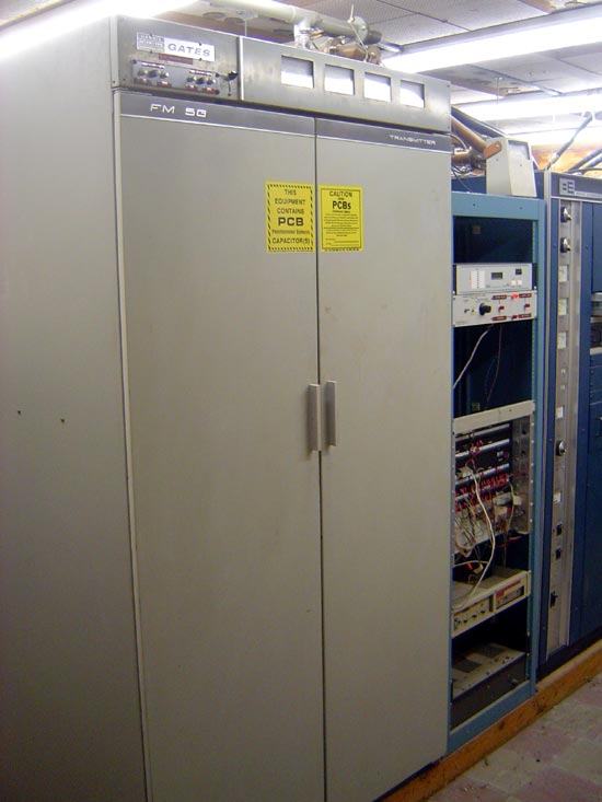
Yesterday, I threw out a transmitter.  I know there is probably some radio station out there that may have been able to use a 5 KW FM transmitter but believe me, not that one.  There are limits to how much you can help out a fellow broadcaster.  Donating an FM transmitter that never really worked right in the first place is counterproductive.

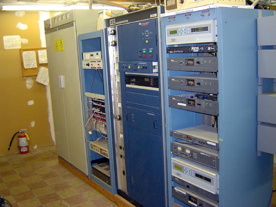
Anyway, to demonstrate that I am not a total heel, here is my favorite brand of transmitter, Nautel:

Nautel V-40 transmitter (4 V-10 transmitters combined)

I like Nautel because they are rugged, reliable, and good-looking.  Okay, good-looking is low on the list of transmitter attributes, however, you have to admit, it is good looking.  It is also good sounding.  The night we switched over from the long-in-the-tooth BE FM30A to the Nautel V-40 I noticed a marked improvement in the station’s sound.  It was like somebody switched off the background noise generator.

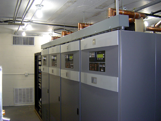
As the caption states, this is 4 V-10 transmitters combined with an ERI magic T combiner.  It is set up so that if any one transmitter fails or reduces power, the magic T combiner automatically adjusts for minimum rejected power, then the SC-1 controller turns up the other three transmitters to maintain the station’s Transmitter Power Output (TPO).

TPO 28 KW
TPO 28 KW

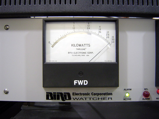
In this case the TPO  is 28 KW, which is getting into the semi serious range for an FM station.   Nautel has updated their transmitter line, which now consists of the NV series transmitter.  The differences mainly have to do with the IPA module/PA module interchangeability (not interchangeable in the V series, fully interchangeable in the NV series) and the “Advanced User Interface.”  I don’t know, fancy touch screens are optional on FM transmitters as far as I am concerned.  It’s the underlying RF generating sections that I am most concerned about.

Nautel V-40 transmitter

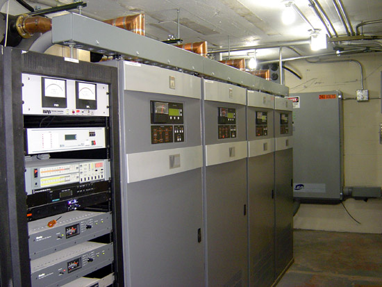
Another view.  Just for the useless trivia that is in it, the “V” in these transmitter names stands for “Virtuoso.”

Gates FM5G transmitter

Takes its rightful place in the world today, the scrap heap:

Gates FM5G carcass
Gates FM5G carcass

As EDWARD I of ENGLAND once said, “A man does good business to rid himself of a turd.”

Of course, he was speaking about Scotsman John Balliol and not some old cranky FM transmitter, but I understand that feeling.  The Gates and later Harris transmitters always seemed to be somewhat less than top-notch. The 5G was no exception to this rule.  The final step for tuning the transmitter was to turn off the lights in the room and look down through the screen on top to make sure there were no little arcs in the PA tuning section.  It also had a way of self-oscillating, which could make for some exciting tuning.

Gates FM-5G transmitter prior to disassembly

Goodbye, I will not miss you.

In one of my past jobs, I worked in a RCA town.  I worked there long after the broadcast arm of that company went out of business, however, all of the broadcast transmitters, AM, FM, TV were made by RCA.   I had an RCA FM-20ES1 which was 22 years old, built like a tank and just kept going along.  I think that transmitter was finally destroyed in a fire, caused by it’s replacement transmitter.

Old Collins, Contenental, RCA and even Broadcast Electronics transmitters had some heft to them.  Of course, not every RCA transmitter was well thought out, the amplifuze series of AM transmitters were a maintenance nightmare.

If it ain’t broke, break it

One thing that I find a little annoying is the continuing need to reboot everything at some interval.  Computers in the studio, audio vault servers and workstations, e-mail servers, files servers, network routers, and so on.  Got a problem, first thing to do is cycle the power off and on…

One of the most irritating pieces of equipment is the audio processors on one of our FM stations.  A few years ago, we purchased the whiz-bang Omnia 6 processor.  Every 6 or 8 months the thing losses its mind and sounds terrible.  The station gets all bassy and the high-end sounds distorted.  I have tried everything I can think of to prevent this, including installing a UPS, extra grounding, extra shielding, software updates, etc.  In the end, it just has to be rebooted, which of course, means several seconds of dead air.  Naturally, this processor is at the FM transmitter site, which it is difficult to get to.

Truth be told when it is working, it does sound pretty good on the air, but is it $10,000 dollars better than the older Optimod 8100A?  No, it is not.

The old Orban Optimods sound pretty good as long as they are re-capped and aligned every so often.  If fact, our number one billing station has an AC format and uses an Optimod 8100A and nothing else.  Our other station in the same market uses an Optimod 8100A and a pair of Texar Audio Prisms. In the ten years, I have been working for this group of radio stations, I have never had to reboot the Optimod or the Audio Prisms, they just seem to work continuously without problems. Imagine that.

I have seen this called a “retro audio chain” by some.  Nothing retro about it, but a little care and feeding and I’d stack this equipment up against an Omnia 6 any day of the week and twice on Sunday.

This is a grainy video of an 8100A  in action:

That was taken in our rack room using off-air audio on the rack room speakers and a cheap video camera. You get the idea.

So here is to Frank Foti and his marketing gurus that have sold all of the program directors in America on the need to “update” their air chain processors, because, you know, the Optimod, that is old skool.

Repairing a solid state FM transmitter module

We have a Harris Z5-CD transmitter for one of our FM stations.  Brand H is not my preferred make, however, it was already installed when we bought the station, so I have to live with it.

This particular site gets hit by lightning strikes often.  Normally, it does not affect anything until the transmitter gets turned off for maintenance.  Then, almost invariably, when turning the transmitter back on one of the modules will fail.  Most often this is manifest when one of the two power supplies shut down causing the transmitter to run no more than 20% power.

The way this is troubleshot is to slide each module out and turn the transmitter back on.  When the power supply stays on, the bad module has been located.  A confirmation test is to check the MOSFET for a short circuit between Drain and Source.  This short circuit condition puts a direct short on the power supply causing it to crowbar and turn off.

So, once the bad module has been located, and the spare module is installed in the transmitter, then what?  Most engineers call Harris and ship the module back for repair.  Most engineers don’t want to mess with unsoldering a surface mount MOSFET and soldering a new one in.   I find it moderately entertaining to fix things myself, so I do not do what most engineers do.

NXP BLF177 MOSFETS
NXP BLF177 MOSFETS

The MOSFET in this particular module is the BLF177, made by NXP.  Harris will sell you one for quite a bit of money.  You can also buy one from Mouser for about half the cost.

Harris FM Z series transmitter PA module with cover removed

Once the parts are obtained, the worst part of the entire job is unsoldering the old MOSFET.  This takes some patience and skill.  What I found works best is to melt some solder on the foil leads and get them good and hot.  Since this MOSFET is already destroyed, we don’t have to worry about heat, etc.  The one thing you do not want to do it actually break the MOSFET open.  That is because it contains beryllium oxide, a known carcinogen.  Once all the solder is liquid, carefully pry the foil up with a small screwdriver.  There are several components that have to be moved to work on this.

Harris Z series PA module with MOSFETS removed

After the old MOSFET is removed, clean up the solder pad with a solder pump and solder wick.  I like to use a little liquid flux on the solder wick, it makes things go faster.

Once all the old solder is cleaned off the solder pads, I brush a light coat of liquid flux in the pad.  Again, this makes things go faster.

Harris Z series FM transmitter module new MOSFETs waiting to be soldered

The new MOSFETS are very sensitive to static discharge, so I always use a static drain wristband when handling them.  I place both MOSFETs onto the circuit board.  I then solder them on using as little heat as possible from the soldering iron.  Again, the MOSFETs are sensitive to heat and one can easily be destroyed if it gets too hot.

Harris Z FM series PA module repaired

This is the module with the new MOSFETs soldered in. I use defluxing compound to remove all the extra flux. Once it cools off, I test the new module with a DVM:

Harris Z series FM PA circuit board under test, resistance is 3.3 Mohm

If the MOSFETS are good, they will have an internal resistance of around 3.3 MΩ.  If the module is bad the MOSFETS will read only  a few ohms if shorted:

Harris Z series FM PA module under test, DVM reads 1.6 ohms

That is how you do it.  I think Harris charges $775.00 per module to repair.  I fixed this one for $240.00, but that is not the reason I did it.  I did it for the fun that was in it.