It’s the middle of the night and the phone is ringing. That is never good. The transmitter is off the air. You call the remote control and try to put the main transmitter back on the air. No good. The backup comes up, no problem. Shaking off the sluggishness, you get dressed and head out the door. The transmitter is about 30 miles away, but it’s in the middle of the night, so there is no traffic. While driving, you are thinking of all the things that could be wrong. The blower motor was sounding a little loud last trip. The exciter has some reflected power. The PA tube is two and a half years old.
Upon arrival, there are several overload lights lit, including the driver’s plate. An investigation is in order. You turn everything off and open the doors. The trouble seems to be a bad IPA power supply. There are spares on the parts shelf, so you put one in. Put the transmitter into the dummy load. You turn on the filament and the transmitter comes to life again. Reset the overloads.
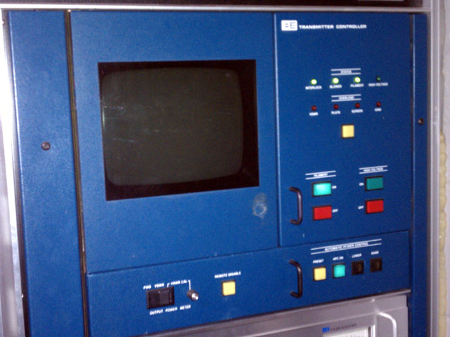
Broadcast Electronics FM35A transmitter ready to be turned on
Now you are standing there looking at the plate-on button. Was it really only the IPA or was that just a symptom? Was there something else that took out the IPA power supply? What will happen when I press the plate-on button? Will it come on normally or go BANG! I hate BANG! By the way, my tradition in a situation like this, if on a mountain top somewhere, I go outside and pee. I give the situation one more run through the mental checklist, then come back inside and press the button.
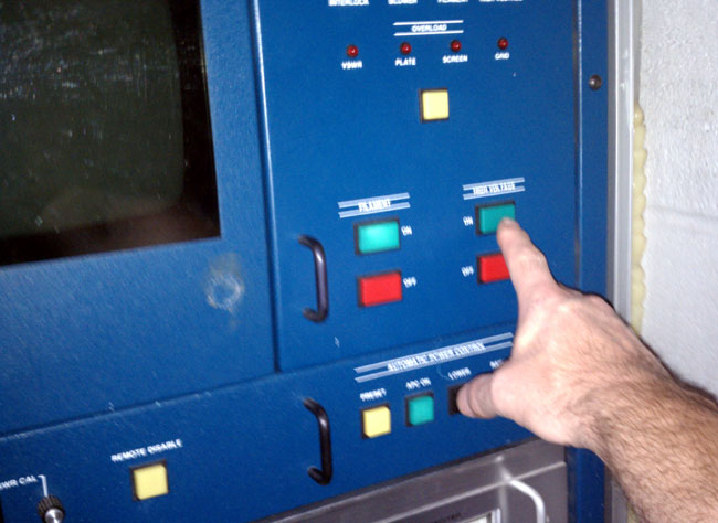
Broadcast Electronics FM35A transmitter high voltage on button
Please excuse the blurry picture, it is hard to take a picture of yourself turning on a transmitter…
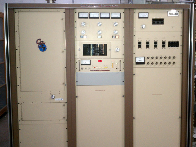
This is perhaps my favorite model FM transmitter, the Continental 816R2:
Continental 812R2A transmitter, on the air
I have known this particular transmitter for almost twenty years. It was installed new at WFLY 92.3 MHz in August of 1986. I was reflecting on that today, as I replaced the bad 4CX250B driver tube which caused the output power to drop to 10 percent. The power control is via SCRs on the HV power supply, not the more common PA screen voltage adjustment. That means the transmitter comes on with zero PA voltage and ramps up to full power. It makes the whole thing “smooth” like driving a Mercedes.
I have experienced a few overloads, which usually are accompanied by the room lights dimming slightly and the plate voltage turning off. Again, no theatrics; no big blue flashes, no loud arcs, etc. Simply turns off the high voltage and light a LED on the overload board to tell the operator what happened.
Over the last 20 or so years, I think I have had three out-of-the-ordinary problems with this transmitter:
The power supply pass transistor in the 802 exciters failed. This is a TO-3 case mounted on a heat sink, something like a 2N2225 I think. It runs hot. Anyway, the exciter had no 20-volt supplies, which was pretty easy to diagnose.
The SWR foldback did not work during an ice storm. This transmitter feeds an ERI antenna without heaters or radomes. About once every 2-3 years there is an ice buildup, which will cause the transmitter to fold back. In this case, the transmitter overloaded and went off the air instead. Traced back to a bad/dirty connector on the directional coupler.
One of the SCRs exploded while running on the generator. Figured out this was caused by harmonics from the generator exciter. Replaced the exciter with a different version, no SCR problems were encountered after this fix.
I like the Continental tube-type transmitters, they are solid units that perform well and have years of reliable service if properly maintained.
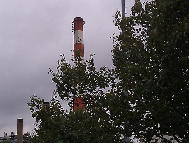
If a person were to drive south down I-95 through Bridgeport, CT and look off to the left, they would see a 500-foot smokestack for a coal-fired power plant. Side mounted on that smokestack is a 6-bay Shively FM antenna. The antenna is more visible when driving south. That would be the antenna for WEBE 107.9 Mhz. This is right downtown, therefore, I would imagine this station has no problems with reception.
Bridgeport Power Plant smokestack, viewed from the west
WEBE is a class B FM with a full 50 KW ERP. Most FM’s around here take advantage of a nearby mountain to gain some altitude and thus reduce the TPO a bit. There are several class B stations that run less than 5 KW into a relatively small antenna, but they are way up in the 900 to 1000-foot HAAT range. In this case, the power plant is located right on the Pequonnock River Bay, so the AMSL at the base of the smokestack is only 10 feet. This means lots of watts out and a fairly large antenna.
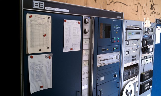
They are using Broadcast Electronics FM35A for the main and backup transmitters. They were installed in late 1986 and are a little long in the tooth.
Broadcast Electronics FM35A transmitter
They run near a 12 KV plate supply, about 3.8 amps making 34 KW TPO. That goes into a six bay Shively 6 bay 6813 antenna centered at 475 feet, which makes the HAAT 117 meters.
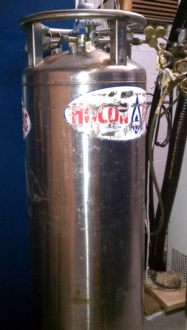
One of the problems encountered at the site is the smokestack emissions. It seems that a fair amount of mercury comes out to the top of that thing. In the past, this has caused major problems with the antenna shorting itself out and burning up transmission line. Because of this, the entire antenna system, radomes, and transmission line is supplied with Nitrogen from this liquid nitrogen tank:
Liquid Nitrogen Tank
The antenna then intentionally bleeds N2 into the radomes continuously, overpressurizing them, to keep the smokestack emissions out. This type of tank is needed because a conventional N2 tank would last about a day, whereas the liquid tank lasts about 20 days.
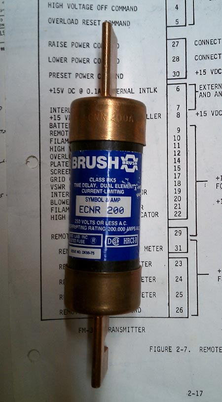
The BE FM35A decided to blow a 200 Amp fuse on Friday afternoon:
Blown 200 Amp fuse
I had a BE FM30A that would randomly trip the 200 amp main breaker every once in a while. I could never find anything wrong with the transmitter, it would just come back on and run normally again after the breaker was reset. I even replaced the breaker thinking breaker fatigue. Still happened. In the end, we replaced that transmitter. In this case, I don’t see that happening anytime soon.
BE FM35A heavy iron:
Broadcast Electronics FM35A plate transformer
I would not want to replace this thing, it must easily weight 1,000 pounds.
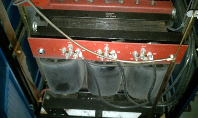
And rectifier stacks:
Broadcast Electronics FM35A rectifier stacks
12,000 volts DC. That will light up any dirt, dust, piece of fuzz, etc. in the transmitter.
It is one of the more unique FM transmitter sites I’ve ever been to. Every time I see it, I am reminded of that song, Smokestack Lightning. My favorite version of that song is the live recording by the Yardbirds
As broadcasters, we don’t really hear that much about ceramic power vacuum tubes these days, as more and more broadcast transmitters migrate to solid-state devices. Once upon a time, however, power tubes were the engine that drove the entire operation. Tubes had to be budgeted for, stocked, rotated, and replaced on a regular schedule. Some of those dern things were expensive too.
Take the 4CX35,000A which was used in the Harris MW50 transmitters. The transmitter used two of these tubes, one in the RF section and one in the modulator. As I recall, new tubes cost somewhere north of $8,000.00 each from EIMAC. Plus, in the A models, there were two 4CX1500A driver tubes. All of which could add up to an expensive maintenance cost every two years or so.
The next best option was to buy rebuilt tubes. Rebuilt tubes were about half the cost of brand-new ones. Some people complain that rebuilds don’t last as long, or only last half as long as the new tubes. I never found that to be the case. I often found other factors that affected tube life far greater, such as filament voltage management, cooling, and by extension, cleanliness.
I can say I never had a warranty issue with ECONCO tubes. I cannot say that about EIMAC, as during the late 90s and early ’00s (or whatever you call that decade), I had several brand new 4CX3500 tubes that were bad right out of the box. These days, ECONCO and EIMAC are both owned by CPI.
I spoke with John Canevari from ECONCO who had a lot of information. For example, as the tube ages, the filament gets more flexible, not less. Most ceramic power tubes use a carbonized tungsten filament containing some small amount of thorium. As the tube ages, the filament can no longer boil off enough electrons and the emission begins to drop off. That is the normal end of life for a power tube. Occasionally, some catastrophic failure will occur.
There are many steps in the rebuilding process:
Dud is received from the field, the serial number is recorded and the tube is tested in.
The tube is prepped by sand-blasting the sealing rings
It is opened
The filament is replaced. In 60-70% of the cases, the grid is replaced. In those tubes that have a screen assembly, 20-60% of those will be replaced.
The Interior of the tube is cleaned
The tube is resealed and tested for leaks with a gas spectrometer
The tube is placed on the vacuum machine. Tubes are evacuated hot, smaller tubes take 12 to 24 hours, and very large tubes can take up to one week.
The tube is nipped off of the vacuum while still hot. When the tube is fully cooled the vacuum scale is normally around 10-12
The exterior of the tube is cleaned and replated. Silver for tubes that are socketed and Nickel for tubes that have leads.
The tube is retested to the manufacturer’s original specification or greater.
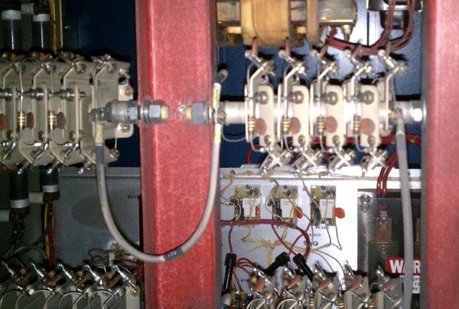
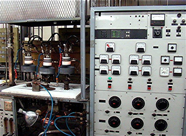
After that, the tube is sent back to its owner or returned to stock. John mentioned that they are very proud of their vacuum tube processing machines, so I asked if he could send along a picture. They certainly look impressive to me, too:
Vacuum tube processing machine, photo courtesy of ECONCO
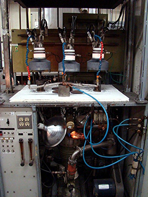
Not exactly sure which tube type these are, but they sure look like 4CX15,000:
Vacuum pump working on rebuilt ceramic power tubes, photo courtesy ECONCO
Econco has been in business since 1968 and rebuilds about 600-1,000 tubes per month. In the past, broadcasters used most of the larger tube types. However, with the majority of broadcast transmitters shifting to solid state, other markets have opened up such as industrial heating, military, research and medical equipment.