Rebuilt tubes

As broadcasters, we don’t really hear that much about ceramic power vacuum tubes these days, as more and more broadcast transmitters migrate to solid-state devices.  Once upon a time, however, power tubes were the engine that drove the entire operation.  Tubes had to be budgeted for, stocked, rotated, and replaced on a regular schedule.  Some of those dern things were expensive too.

Take the 4CX35,000A which was used in the Harris MW50 transmitters.  The transmitter used two of these tubes, one in the RF section and one in the modulator.  As I recall, new tubes cost somewhere north of $8,000.00 each from EIMAC.  Plus, in the A models, there were two 4CX1500A driver tubes.  All of which could add up to an expensive maintenance cost every two years or so.

The next best option was to buy rebuilt tubes.  Rebuilt tubes were about half the cost of brand-new ones.  Some people complain that rebuilds don’t last as long, or only last half as long as the new tubes.  I never found that to be the case.  I often found other factors that affected tube life far greater, such as filament voltage management, cooling, and by extension, cleanliness.

I can say I never had a warranty issue with ECONCO tubes.  I cannot say that about EIMAC, as during the late 90s and early ’00s (or whatever you call that decade), I had several brand new 4CX3500 tubes that were bad right out of the box.  These days, ECONCO and EIMAC are both owned by CPI.

I spoke with John Canevari from ECONCO who had a lot of information.  For example, as the tube ages, the filament gets more flexible, not less.  Most ceramic power tubes use a carbonized tungsten filament containing some small amount of thorium.  As the tube ages, the filament can no longer boil off enough electrons and the emission begins to drop off.  That is the normal end of life for a power tube.  Occasionally, some catastrophic failure will occur.

There are many steps in the rebuilding process:

  1. Dud is received from the field, the serial number is recorded and the tube is tested in.
  2. The tube is prepped by sand-blasting the sealing rings
  3. It is opened
  4. The filament is replaced.  In 60-70% of the cases, the grid is replaced.  In those tubes that have a screen assembly, 20-60% of those will be replaced.
  5. The Interior of the tube is cleaned
  6. The tube is resealed and tested for leaks with a gas spectrometer
  7. The tube is placed on the vacuum machine.  Tubes are evacuated hot, smaller tubes take 12 to 24 hours, and very large tubes can take up to one week.
  8. The tube is nipped off of the vacuum while still hot.  When the tube is fully cooled the vacuum scale is normally around 10-12
  9. The exterior of the tube is cleaned and replated.  Silver for tubes that are socketed and Nickel for tubes that have leads.
  10. The tube is retested to the manufacturer’s original specification or greater.

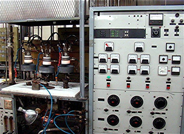
After that, the tube is sent back to its owner or returned to stock.  John mentioned that they are very proud of their vacuum tube processing machines, so I asked if he could send along a picture.  They certainly look impressive to me, too:

vacuum tube processing machine
Vacuum tube processing machine, photo courtesy of ECONCO

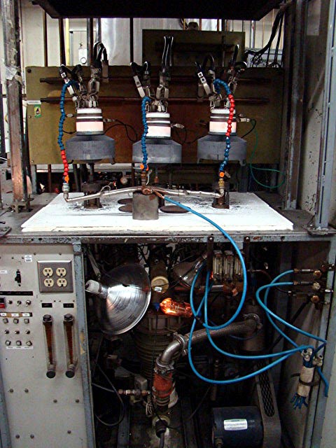
Not exactly sure which tube type these are, but they sure look like 4CX15,000:

vacuum pump on rebuilt ceramic power tubes
Vacuum pump working on rebuilt ceramic power tubes, photo courtesy ECONCO

Econco has been in business since 1968 and rebuilds about 600-1,000 tubes per month.  In the past, broadcasters used most of the larger tube types.  However, with the majority of broadcast transmitters shifting to solid state, other markets have opened up such as industrial heating, military, research and medical equipment.

RCA BTF-20E

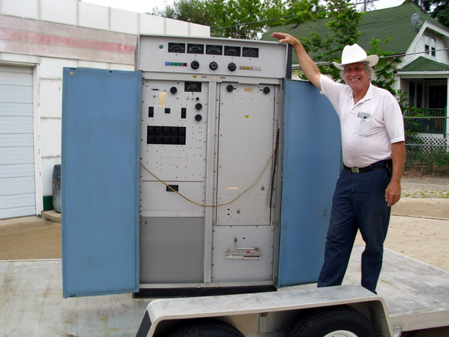
Does anyone need any parts for one? Long-time reader and commenter John has one that looks to be in good shape that he is willing to part with or part out.  I had three of these units in Harrisburg and my recollection is they were pretty solid units.  When tuned properly, they were low noise and sounded good on the air.

The one issue I had was with the small 100 pf pass-through/by-pass capacitors in the IPA.  Several went bad and were no longer functioning as bypass caps.  The result was the transmitter would self-oscillate.  I think there were seven or eight of them and I replaced them all at once.  The exact model of that particular transmitter was a BTF-20ES1, which was one of the last FM transmitters off of the factory floor before the broadcast division went under.

RCA BTF-20E FM transmitter
Late model RCA BTF-20E FM transmitter

John says:

If anyone needs parts out there, I will probably cannibalize this unit as I have just too many. The separate power supply is inside the garage along with the latest version of the harmonic filter entirely made of copper.

I don’t know if the entire unit actually runs or if it is parts only.  It certainly looks like a clean unit.  As I recall, Comark bought out all the RCA broadcast parts and service. Comark was then sold to Thomcast, which was sold to Thales which I think spun off its transmitter division to Grass Valley Group.  Grass Valley started by making TV master control switchers, routers, and other video equipment.

Anyway, if you are looking for RCA parts for FM transmitters, contact me, and I’ll put you in touch with John.

Harris FM25-K

Old blue, I like to call them, the Harris 1980s model transmitters with black faces, white cabinets, and blue trim. I have yet to find one that I really like, the FM 25-K is, well okay. Sort of like that 200,000-mile jeep that works, most of the time, and it’s paid for.
This particular FM-25K transmitter is located at WIZN in Charlotte, VT.

Harris FM25-K transmitter

This transmitter was new in 1987.  It had a bad day yesterday, deciding to throw a temper tantrum and trip the HV power supply breaker.  Fortunately, the station has a backup transmitter.  When we arrived, we found the HV power supply feed through the insulator at E1 arced over and broken.  Again, fortunately, this station’s management believes in stocking spare parts and a replacement was on hand.

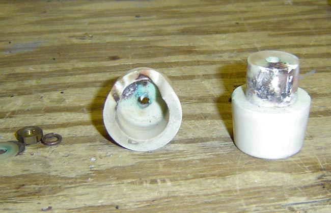
Harris FM25K HV power supply feed through insulator

This is part of the RF filter for the HV power supply. This happened once before, about two months ago. The replacement insulator then was used, so that might be a factor. Two months ago, both capacitors in the Pi filter and the HV power supply cable (RG-8 coax) were replaced all the way back to the rectifier stacks.

The FM25-K can produce spontaneous high-frequency oscillations if not tuned properly.  We looked at the transmitter output with a Rode Schwartz spectrum analyzer and found it to be clean.  Exactly why it blew out another feed-through insulator is a bit of a mystery.  Since the first replacement was a used part, we surmise that it may have been cracked.  If this replacement insulator arcs, there needs to be a full investigation.

As I said in the beginning, I have found these transmitters to be okay, not the best, not the worst.  Most of the problems I have encountered with the K series FM transmitters had to do with the controller cards.  There are two, one analog and one digital.  That’s what Harris calls them anyway.  Like the SX transmitter, and the MW transmitter to a certain extent, the control circuits are way over complicated and full of +/- 5 volt CMOS logic.   Having that type of control logic connected to a radio tower (e.g. lightning rod) is asking for trouble.

The sad story of WCVR

I have been the road warrior lately if you haven’t noticed a certain decline in the blog posts… One place that seems to keep pulling me back is Randolph, VT, which is about as close to the geographical center of Vermont as one can get and still be on a roadway.   There resides the silent FM station formerly known as WCVR, to be returned to the air as WXVR by Vermont Public Radio.

WCVR sometime in the early 1980's

WCVR went on the air in 1982 and was a community-oriented country station for 17 years.  Then in 1999, it was sold to Clear Channel and things began to go downhill.  Over the next decade, the station transferred ownership four times.  Finally ending up with absentee landlord Vox Radio.  By the time the station was sold to Vermont Public Radio last May, the years of neglect were compounded and the main transmitter was no longer running.  The transmitter site was raided before the transfer and things like spare parts, a backup transmitter, and a dummy load were removed.  As one engineer from VPR noted, the only thing of any value is the Shively antenna.

This story probably repeats itself a thousand times throughout the country as a small market, formerly community radio stations are left to die on the vine by big-time corporate radio gurus in Atlanta, San Antonio, and Las Vegas.

Said station has a McMartin BF5-K transmitter that is not currently running and by the accumulations of dirt, debris, and other evidence, has not run in quite some time.

The beauty of a McMartin FM transmitter is it is a grounded grid.  Can’t get much simpler than that when it comes to FM transmitters.  The downside is, of course, McMartin has been out of business for almost thirty years.  Thankfully, Goodrich Enterprises is still around and still supports them.

The first order of business was cleaning out the filthy, and I mean absolutely filthy building.  Several hours with a broom, dustpan, and shop vac got rid of most of the dirt and made my skin less likely to crawl.  Then came the fateful attempt to run the transmitter.  Loud arcs, power supply hum, and dimming lights revealed that all was not well.  All of the fluorescent lights were out, new bulbs did not fix the problem.  So, to the Grainger to pick up new fixtures and install them.  Now, at least, we could see what were doing.

Next, step-by-step troubleshooting of the High Voltage power supply.  Step one, resistance checks on the HV transformer and filter chokes to the ground.  Next forward and reverse resistance checks on the rectifier stacks.  All of those looked good.  Next, we isolated the HV transformer and the rectifiers and turned the transmitter on; no problems.  Next, we added the metering and filtering capacitors and turned the transmitter on; no problem.  Finally, we found the problem with the HV power supply RF filter on the side of the PA enclosure.  In a McMartin FM transmitter, there is a little box mounted on the outside of the PA enclosure that holds half the parts in this circuit.  Taking that box off revealed a bad 200 pf 7.5 KV doorknob capacitor that was shorting to ground.  Lots of arc marks, soot, debris, and other stuff make me think that this problem had been going on for a long time.   I can kick myself for not taking a picture.

Hopefully, this thing will run for a few months while a replacement is sought.

Compounding that issue is the leaking transmission line connector at the bottom of the antenna, which was fixed, but there appears to be another leak somewhere else as the line still does not hold pressure for very long.

VPR is going to broadcast their Classical Music format on this station, starting as soon as we can make the transmitter run.

UPDATE: Pictures:

300 foot WCVR tower, Randolph Center, VT

Transmitter building:

WCVR Mc Martin BF-5K transmitter:

Arcing power supply filter section, the bad door knob capacitor has been replaced, still evident are the arc marks on the PA cavity:

Mc Martin BF-5K transmitter on the air:

We’ll see how long that lasts.