Every good transmitter, tube transmitters, in particular, require harmonic filtering. The last thing any good engineer or broadcaster wants is to cause interference, especially out-of-band interference to public safety or aviation frequencies. All modern transmitters are required to have spurious emissions attenuated by 80 dB or greater >75 kHz from the carrier frequency. In reality, 80 dB is still quite high these days, especially in the VHF/UHF band, where receivers are much more sensitive than they used to be. A good receiver noise floor can be -110 dB depending on local conditions.
The principle behind a low pass filter is pretty easy to understand. The desired frequency is passed to the antenna, while anything above the cut-off frequency is restricted and shunted to ground via a capacitor.

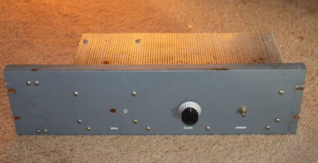
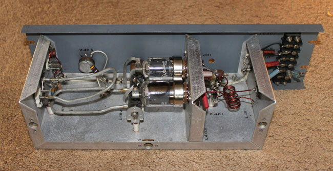
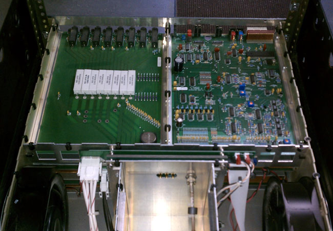
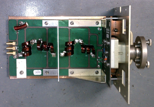
In this case, the resistor is actually an inductor with high reactance above the cut-off frequency. Often, these filters are lumped together to give better performance. This is a picture of an RVR three-stage low pass filter:
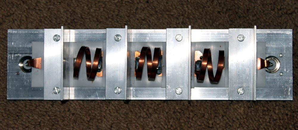
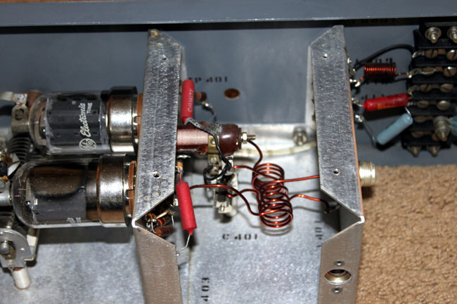
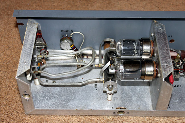
RVR is an Italian transmitter maker that sells many transmitters and exciters in this country under names like Bext, Armstrong, etc. The inductors are obvious, the capacitors consist of a copper strip sandwiched between teflon insulators held down by the dividers in between the inductors.
Schematically, it looks like this:
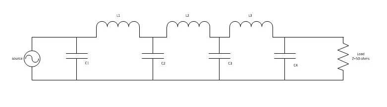
For the FM broadcast band, a good design cutoff frequency would be about 160 MHz. This will give the filter a steep skirt at the first possible harmonic frequency of 176 MHz (88.1 x 2 = 176.2).
Values for components:
| Capacitors | Value | Inductors | Value |
| C1 | 20 pf | L1 | 74.7 nf |
| C2 | 54 pf | L2 | 75.1 nf |
| C3 | 54 pf | L3 | 73.9 nf |
| C4 | 20 pf |
The inductors are wire, or in this case copper strap, with an air core. It is important to keep the transmitter power output in mind when designing and building these things. Higher carrier powers require greater spacing between coil windings and larger coil diameters. This particular filter is rated for 1 KW at 100 MHz.