The side mounted FM antenna

In an interesting development, the FCC has taken notice of some pattern distortion from the side-mounted FM antenna of KFWR, Jacksboro, Texas.  For those, like myself, not familiar with Texas Radio, that is in the Dallas/Fort Worth market.  The crux of the issue is co-channel interference to KCKL in Malakoff, Texas.  These two locations meet the spacing requirements in 73.207 (215 km).  The issue is with the side-mounted ERI antenna and what appears to be intentional pattern optimization.

From the FCC order to show cause:

ERI’s president, Mr. Thomas Silliman, acknowledging that KFWR’s antenna “was mounted in a favorable direction, but… has not been directionalized and therefore is legal.” Mr. Silliman adds that the custom lambda tower at the top of the new KFWR tower was specifically designed for operation at KFWR’s frequency of 95.9 MHz, and that the tower’s lattice structure is “repetitive at the half wave of the specified FM frequency.” Thus, “if one picks a favorable mounting position on the tower, every element in the array sees the same favorable mounting result. Mr. Silliman also states that vertical parasitic elements are used to make the vertical radiation pattern “more circular” and reduce the vertically polarized gain to the east. In a subsequent pleading, ERI elaborates that its computed values “are relative to an RMS measured field of 1.0.” Mr. Silliman concedes that the mounting of the antenna on a certain tower face constitutes “pattern optimization,”arguing later that this is a common practice used by all antenna manufacturers, but states that it is the ERI’s policy “not [to] increase the directivity of the antenna pattern.”

The FCC concludes that the directionality of the side-mounted antenna, in this case, is clearly intentional. The radiated power towards co-channel KCKL was calculated to be 274.5 KW, which is in excess of the 100 KW limit, and orders KFWR to reduce TPO from 25 KW to 9.1 KW.

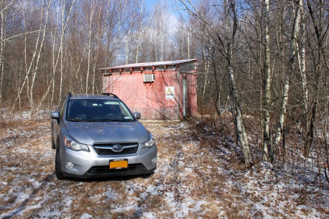
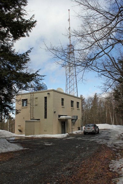
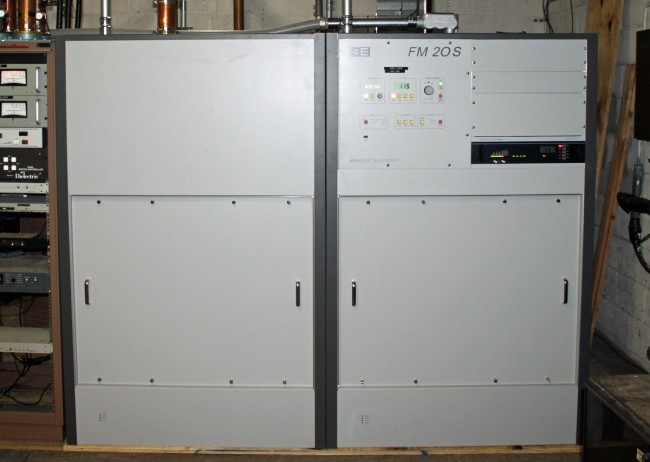
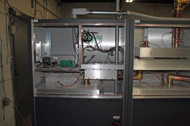
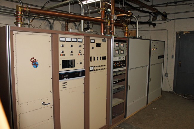
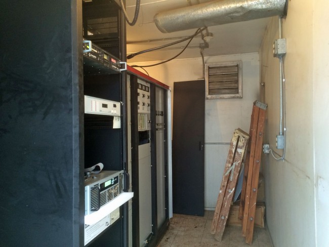
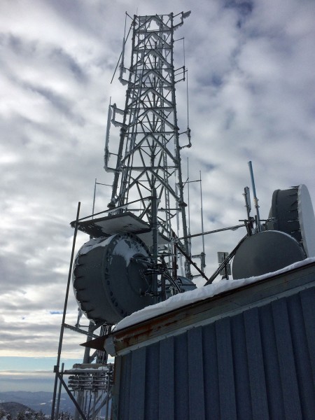
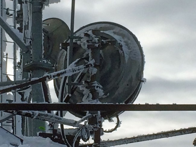
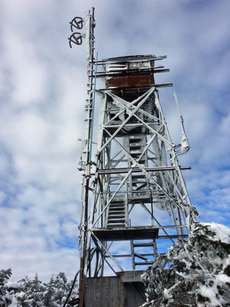
We have lots of these out in the field:

Side-mounted Shively 6810 antenna.  WSPK, Mount Beacon, NY
Side-mounted Shively 6810 antenna. WSPK, Mount Beacon, NY

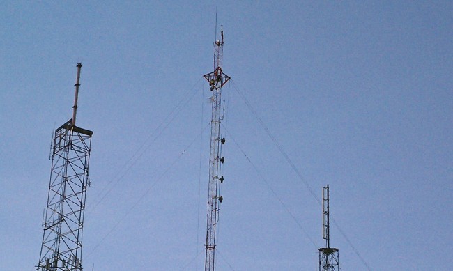
In fact, I believe the majority of our FM stations use side-mounted antennas.  Some of them are mounted to a leg and some are mounted to a face.  Usually, I try to place the antenna on the tower so that the bays are facing the desired audience.  This information is given to the manufacturer when ordering the antenna so that proper mounts can be furnished and the mounting distance between the tower and antenna properly calculated.  That is about the extent of any “optimization” that is allowed.

As the FM band gets jam-packed with FM signals, this may become more of an issue in the future, particularly around dense signal areas around major metropolitan areas.

Transmitter site re-hab

One of the reasons for the recent lack of posts; I have been busy rehabilitating several transmitter sites for various broadcasting companies. These are mostly FM transmitter sites and vary in power from one kilowatt to twenty-six kilowatts ERP.  I enjoy project work, but I have been driving hither and yon, racking up 27,000 miles on my new car since last August.

Subaru Crosstrek XV at remote transmitter site, somewhere in rural New York

So, here is one transmitter site that I just finished; WFLY, Albany, New York.  Removed Collins 831F2 transmitter which was functioning as a backup and installed new Broadcast Electronics FM20S.  The Continental 816R2 is becoming a little bit long in the tooth for a main transmitter, being new in 1986.  Thus, it was time to install a new unit, and I like the Broadcast Electronics solid state and tube designs.  With the BE AM and FM solid-state units, their simplicity is their beauty.  We service many BE transmitters, some are thirty years old and are still supported by the manufacturer.

WFLY transmitter building, New Scotland, NY

The BE FM20S transmitter is actually two FM10S cabinets combined with one controller.  Each cabinet requires a 100 amp three-phase mains connection.  This station’s TPO is 11.5 KW, so there is plenty of headroom in case the owners ever want to install HD Radio or replace the three-bay antenna with a two-bay unit.

WFLY main transmitter, Broadcast Electronics FM20S

In transmitter cabinet two, above the exciter is room for HD equipment.

BE FM20S exciter housing

I also reworked the coax switches to provide an easier implementation of the backup transmitter.  Basically, the main transmitter is on the main antenna, and the backup transmitter is on the backup antenna.  We can move the second coax switch to test the backup into the dummy load.  We can move the first coax switch to change antenna feeds.

WFLY backup and main transmitters

Pretty standard setup.

WFLY RF path diagram

We moved the Collins 831F2 from Albany to here to replace another, dead Collins unit at WKXZ in Norwich, New York.  This transmitter is forty years old but still runs reliably.  Of course, doing this work in the dead of winter added a degree of difficulty to the job, as the roads to both the WFLY and the WKXZ transmitter sites needed work to make them passable for a moving truck.  In the end, we used a skid steer with forks on it to get the transmitter up the final hill and into the small WKXZ transmitter building.

Collins 831F2 transmitter, WKXZ, Norwich NY
Collins 831F2 transmitter

The WKXZ transmitter building interior is floor space challenged. It is located next to a former TELCO microwave site which has a guyed tower.

Winter! Is upon us….

What better time to take the gondola to K-1? None, none at all.  We do work for the two radio stations that are on the peak of Mount Killington, near Rutland, Vermont.  In the summer, usually, we can drive up there in a four-wheel drive truck.  In the winter, the gondola is the way to go.  On this day, there was a 48-56 inch base, light north winds, and air temperature around 10° F (-12° C) .

Ride up to Killington Peak
View from Killington Peak
Transmitter buildings on Killington Peak
View from Killington Peak
Tower from Killington Peak
Killington STL dishes
ERI antenna, WZRT/WJJR Killington VT

The reason for the trip today; is repair work on the Nautel VS2.5 transmitter. All three power supplies and the power supply summing board needed to be replaced.

Village seeks repayment from Energy Onix

This saddens me a little bit.  Apparently, the Village of Valatie, NY is seeking repayment of a $500K loan from Transmitter Manufacturer Energy Onix.  Since the passing of Bernie Wise, the company has basically folded.

The village may foreclose on the building if necessary, said Mayor Diane Argyle.

Located at 1306 River St., Energy-Onix was founded in 1987 by broadcast pioneer Bernard Wise, who is known for bringing the “grounded grid” to radio broadcasting. The company designed, manufactured and sold radio transmitters and tubes.

More from the Columbia-Greene Register Star.

Sadly, there goes support for many Energy Onix and CCA transmitters still in the field.  I know of several of those old CCA transmitters that are still cranking away, 40 or more years after they rolled out of the factory in Gloucester, NJ.   I have tried, several times, to call Energy Onix since Bernie passed last year and the phone goes unanswered.  I wonder if we could pick up the field support and service for these units.  I wonder if there are any spare parts left at the old factory building?