In an interesting development, the FCC has taken notice of some pattern distortion from the side-mounted FM antenna of KFWR, Jacksboro, Texas. For those, like myself, not familiar with Texas Radio, that is in the Dallas/Fort Worth market. The crux of the issue is co-channel interference to KCKL in Malakoff, Texas. These two locations meet the spacing requirements in 73.207 (215 km). The issue is with the side-mounted ERI antenna and what appears to be intentional pattern optimization.
From the FCC order to show cause:
ERI’s president, Mr. Thomas Silliman, acknowledging that KFWR’s antenna “was mounted in a favorable direction, but… has not been directionalized and therefore is legal.” Mr. Silliman adds that the custom lambda tower at the top of the new KFWR tower was specifically designed for operation at KFWR’s frequency of 95.9 MHz, and that the tower’s lattice structure is “repetitive at the half wave of the specified FM frequency.” Thus, “if one picks a favorable mounting position on the tower, every element in the array sees the same favorable mounting result. Mr. Silliman also states that vertical parasitic elements are used to make the vertical radiation pattern “more circular” and reduce the vertically polarized gain to the east. In a subsequent pleading, ERI elaborates that its computed values “are relative to an RMS measured field of 1.0.” Mr. Silliman concedes that the mounting of the antenna on a certain tower face constitutes “pattern optimization,”arguing later that this is a common practice used by all antenna manufacturers, but states that it is the ERI’s policy “not [to] increase the directivity of the antenna pattern.”
The FCC concludes that the directionality of the side-mounted antenna, in this case, is clearly intentional. The radiated power towards co-channel KCKL was calculated to be 274.5 KW, which is in excess of the 100 KW limit, and orders KFWR to reduce TPO from 25 KW to 9.1 KW.
We have lots of these out in the field:
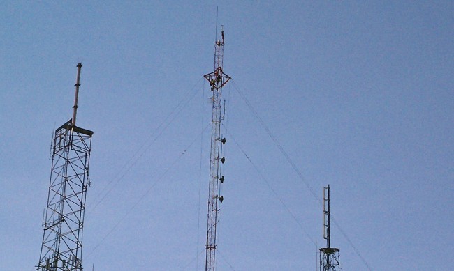
In fact, I believe the majority of our FM stations use side-mounted antennas. Some of them are mounted to a leg and some are mounted to a face. Usually, I try to place the antenna on the tower so that the bays are facing the desired audience. This information is given to the manufacturer when ordering the antenna so that proper mounts can be furnished and the mounting distance between the tower and antenna properly calculated. That is about the extent of any “optimization” that is allowed.
As the FM band gets jam-packed with FM signals, this may become more of an issue in the future, particularly around dense signal areas around major metropolitan areas.

I suppose this type of placement matters little for LPFMs, but I will ask anyway so I can learn: If you were going to mount a two bay, would you point it towards where you think more people are? Or, more concerning, “into” your co-channel interferer? Or away from it? 90 degrees away from the interferer?
If the antenna is mounted on a pole, then it really does not matter which way it faces, it will have an omni-directional pattern. If, however, the antenna is side mounted on a tower, I would face the bays toward the population center you are trying to cover. As in the above example, towers do create pattern distortion, usually by reflecting radiation off of the back of the antenna toward the tower.
Best bet is to find or commission a pattern study for your specific antenna on your specific tower. At bare minimum study the stock pattern drawings most manufacturers offer.
Even small changes in mounting can have large and often unwelcome effects on coverage, pointing the antenna at the desired population may or may not work as intended.
I’ve seen sidemounts with a bulged figure-8 pattern with max power from the sides of the bays, not front/back. Not that anyone would do such a thing intentionally.
Even on a pole mount, you will find that the pattern differs from H-pol and V-pol. While the H-pol is largely unaffected by the pole mount, the vertical component will usually wind up with a null of some kind off the back of the antenna due to the pole and the polarization (vertical) being the same orientation.
Patterns needs to both meet the needs of the audience being served ( there’s a concept..public service),
and need to conform to the engineering presented for the construction / license permit.
Good engineering has always used various “tricks” to optimize.. tilt up or down, nulls and peaks.
But, they should be spec’d and confirmed in the field.
This case, where they used built the support structure to form passive resonant elements of an antenna system, not spec’d in the station license.. is purely corrupt and illegal. Which in the current business and moral environment of the US is just what.. ho-hum ?
We know that the “killer” who sells the most advertising becomes GM… so lets put some long horns on the caddy,
and pop a cold 12 pack on the seat.. and head out.