Well, it certainly looks good:
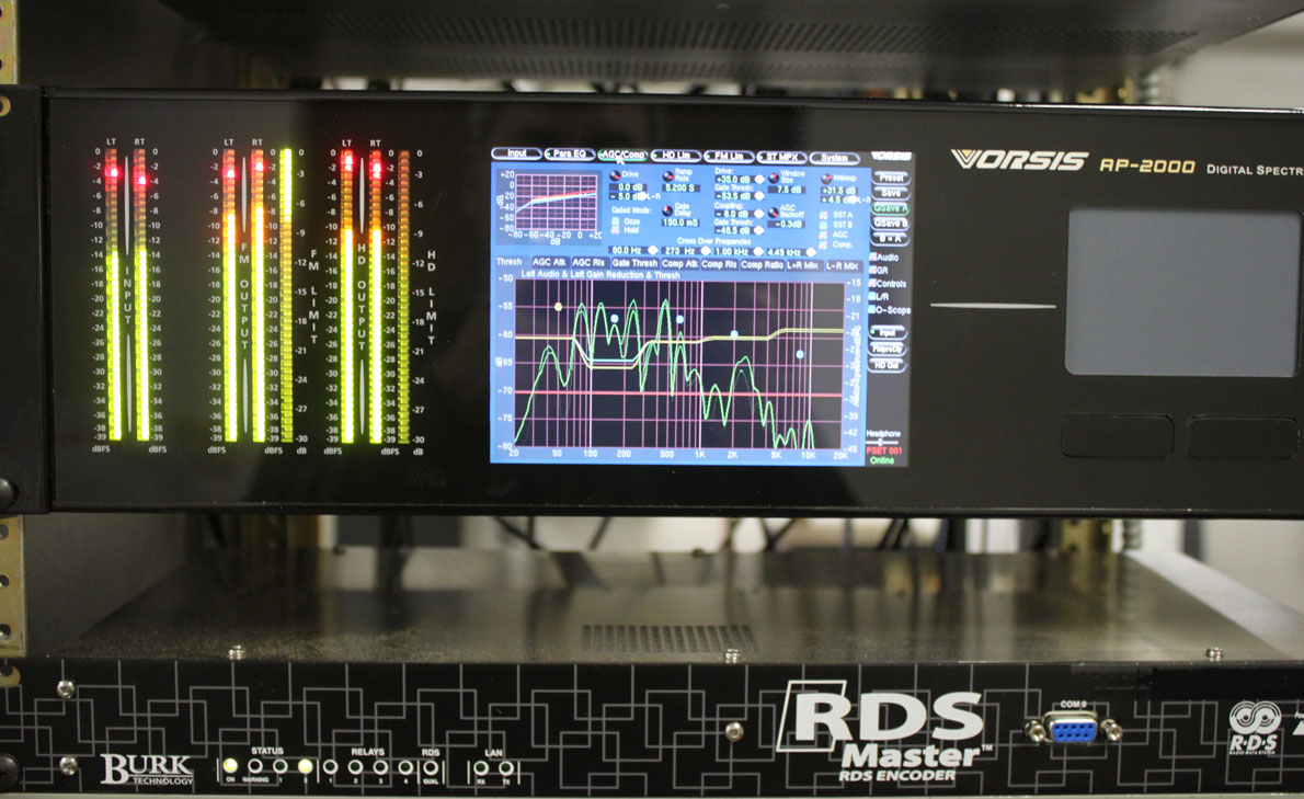
I will have to set up the video equipment and record a song while filming the front panel display. By the way, it also sounds good.
FM broadcast audio processor
Well, it certainly looks good:
I will have to set up the video equipment and record a song while filming the front panel display. By the way, it also sounds good.
A piece of vintage gear from the late 1970’s, the Optimod 8000 was and still is a good sounding box. I have often thought that these processors would make an excellent internet audio processor using the test jacks on the back of the unit. The audio on these jacks is unbalanced and has 75 µS pre emphasis. It would be easy enough to make a de-emphasis network and create balanced audio with a 10K:600 ohm transformer. Some experimentation may be required with the transformer primary impedance value. Orban notes that not less then 1 MΩ impedance should be connected to the test jacks. For the internet station looking to copy the “FM radio” sound, this unit would do the job nicely.
The 75 µS de-emphasis network would look something like this:

In this case, the values for the de-emphasis network are fairly critical, therefore 1% or better tolerances for the resistors and capacitors is required.
Even better, an LPFM or some other radio station on a budget could acquire one of these for relatively little on eBay or somewhere else. With a little TLC, most of these units can be rebuilt and put back into service. I would recommend that some type of limiter be used in front of it, such as a Texar Audio Prism or CRL SEP-800.
Some classical music stations prefer these units. I have noticed that they have a nice, mellow, open sound. Not at all fatiguing and yet still offer a nice easy 10 dB gain reduction. There is also a modification that can slow down the release time on the gain reduction. More gain reduction, AKA compression, can be had with something else in front of the unit.
The best part about these units, there is no rebooting, no processor lock ups, software glitches or any of that non-sense. Additionally, a quick look at the front of the unit shows very few user controls, making it almost impossible to screw up and sound bad. They are well built and so long as the electrolytic capacitors are changed out, fairly bullet proof. Other processors, not so much.

This is an Optimod 8000A that I decided to put through its paces.
Really, how much more do you need? I recorded this on the camera microphone using a replica table radio, seen near the end of the video on the right hand side of the frame.
I used the Technics SL-1200 MKII turntable through an ATI P100 turntable preamp into the Optimod. The Optimod is feeding a BE FX-30 exciter running 15 watts into a dummy load. The Optimod is running about 5-7 dB gain reduction, which is enough in my mind. The BE FX-30 is still just about the best sounding analog exciter every made.

This unit has been re-capped and re-chipped at one point. The re-chipping follows the Orban recommendation; the 4558 and 1556 opamps are replaced by TL071CP and TL072CP respectively, and the uA 709 and 301A opamps are left in the unit. A good thing to remember, the uA709 and 301A opamps can be replaced by TLO71cP opamps in the event of failure. The Texas Instruments TL0 series opamps are very good and readily available.

Overall, this unit is in good condition, however, like many such units, it is missing its brown “Optimod” cover, which goes over the input/output controls.
Manual is available at the Orban ftp site: ftp.orban.com.
There are a few FM stations around here that intentionally broadcast in mono. One is an FM talker, which from a technical standpoint makes a certain amount of sense since any particular human voice is a single-point sound generator.
The other FM station broadcasting in mono, WKZE, has a music format with a very eclectic playlist. It is a full Class A located in northwestern Connecticut. The idea with this station is to garner a larger and more reliable coverage area.
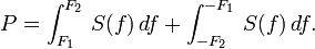
It comes down to a simple physics discussion about free space loss. The basic equation for free space power loss is:

where:
 is the signal wavelength (in meters),
 is the signal frequency (in hertz),
 is the distance from the transmitter (in meters),
 is the speed of light in a vacuum, 2.99792458 × 10⁸ metres per second.
That formula works for a single frequency, say the carrier frequency, for example. As the signal gets spread out by modulation, the power density on any given frequency is reduced as the energy is divided between many other frequencies.
First, free space loss takes into account the spreading out of electromagnetic energy in free space is determined by the inverse square law, i.e.

where:
 is the power per unit area or power spatial density (in watts per meter-squared) at distance ,
 is the total power transmitted (in watts).
Second, with Frequency Modulation (FM), the power spectral density is a function of the differences in the highest and lowest frequency:
Therefore, the narrower the bandwidth of a signal, the higher the density of the received signal will be in relation to the transmitted power. An unmodulated FM signal will have a better, more reliable coverage area than a modulated one. Of course, we need to modulate the signal, otherwise, there is no point in having the transmitter on.
A baseband or composite FM signal has several components:

An FM station transmitting a mono signal will have a much lower bandwidth. With wideband FM, the modulation index is generally 2fΔ or two times the maximum audio input frequency. Thus, a mono FM broadcast station will have an approximate deviation of approximately 30 kHz (plus any ancillary services like RDS) vs a stereo FM station, which has a 75-80 kHz deviation using the same carrier power.
For higher power FM stations, FCC Class C and B, this is not much of an issue. Those stations tend to have a great deal headroom when it comes to power density, building penetration, multipath (picket fencing and capture effect). For Class A and LPFM stations, it is a different situation. For those stations, unless FM stereo broadcasting is truly needed, it should be turned off. On low power stations, stereo can be a great detriment to reliable coverage.
I give to you, the original Texar Audio Prism:
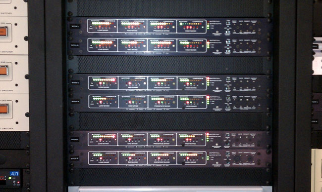
I love the sound of these units when coupled with an Optimod 8100A. Many people have (or rather, had) difficulty setting these things up. I found them to be very easy to deal with, just follow the instruction manual. If that doesn’t sound good, then there is something wrong with the unit. Over the years, there are only a few consistent problems. The first thing is with the voltage regulators. They have heat sinks attached with nylon screws. The screws get brittle and fall apart, making the regulator overheat and go bad. I have taken to replacing the nylon screws, and if the heat sink has fallen off, the entire regulator. There are also a few electrolytic capacitors in the power supply and on the audio board, it is always a good practice to replace those. Otherwise, unless the unit has been blown up by lightning, it should work.
As for set up, follow the directions in the manual:
The rest of the settings are on the Optimod:
Then set the L-R null. To do this, make sure the program material is in mono, then adjust the L or R input attenuator for minimum reading. Also, if the Audio Prism has PR-1 (phase rotators) installed, bypass the phase rotator in the Optimod. There is also a replacement card 5 made by Gentner called the RFC-1 for the Optimod 8100A. I notice little difference between a stock Optimod and an RFC-1 Optimod.
That is a good starting point. Most people are quite happy with this, but if needed, the high and low settings on the Prism can be adjusted slightly to suit the station equipment. When properly adjusted, this equipment rides gain, and adds a certain amount of loudness, while keeping the programming material natural sounding. Further, unlike some “modern” air chain processors, it does not boot up and it does not occasionally lose its mind, requiring a reboot.
The best paragraph in the manual, or any broadcast equipment manual is this:
There is a wealth of information available in the LED display. A few minutes of watching them in reduced light (emphasis added) while listening to a familiar program input will greatly help in understanding their action.
It will also greatly enhance your buzz, dude. It was the 70’s.