It is time, once again, to replace some very old Pacific Recorders BMXII consoles. The Pacific Recorders consoles were very expensive when new, but after 30 years of continuous use, have more than paid for themselves. The replacement console of choice for this installation is a SAS Rubicon. I have installed these units elsewhere and they are the modern equivalent of the PRE BMX.
The heart of the Rubicon system is the 32KD router. Routed audio systems can save a lot of time and effort in a large studio facility installation. Not having to run and terminate multiple analog and digital trunk cables between the rack room and the studio is a huge deal in a six or ten-studio installation project.
The SAS 32KD router and Rubicon console system use a serial TDM bus to communicate and transport audio around. This is a simpler system than packet-switched IP data. Basically, the console surface is a very large, fancy computer control interface. Here are some pictures of the start of the project:
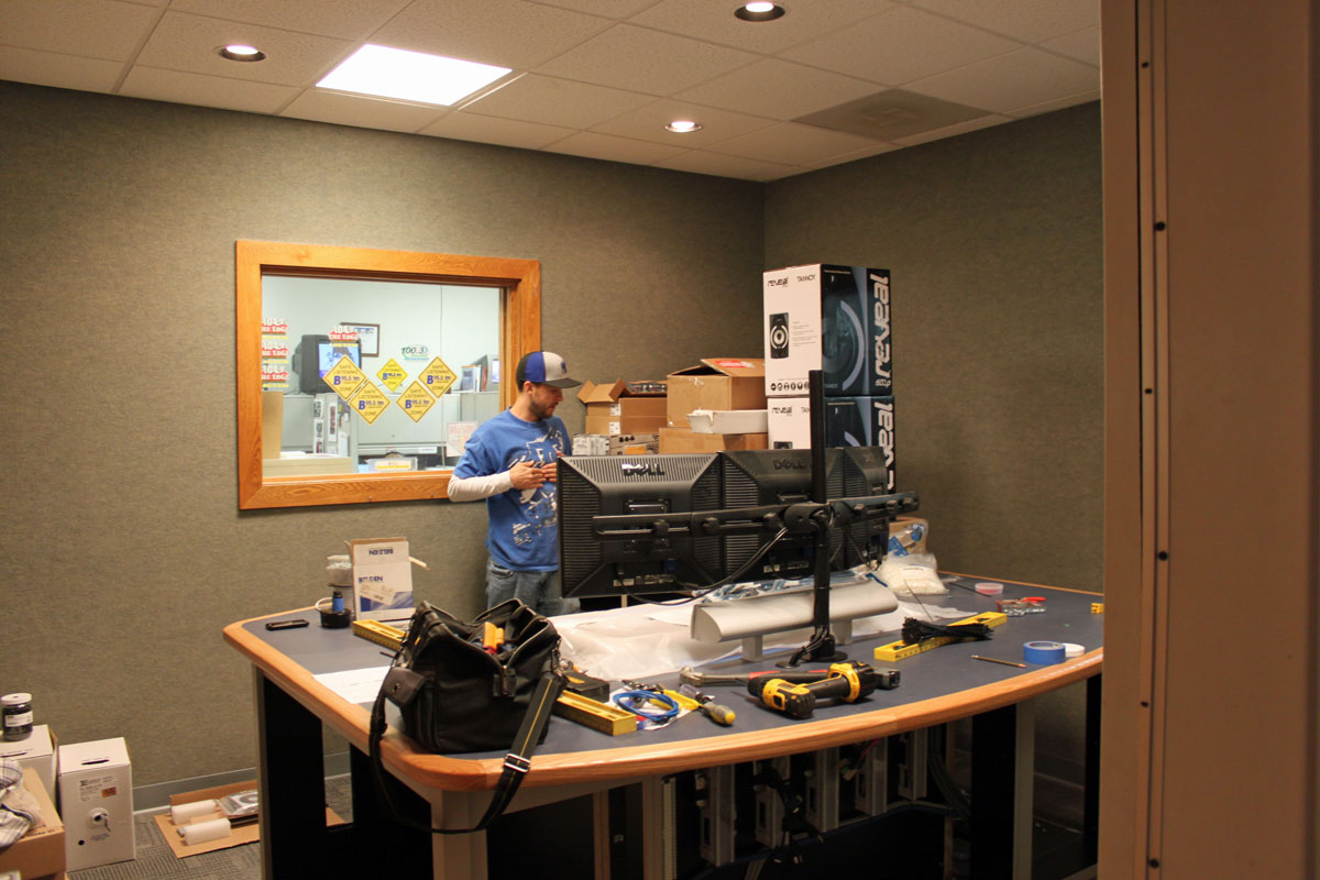
New Studio room, furniture installed
This is the view from the entry door. The furniture was placed last week and the countertop was cut in for the console. The furniture is made by Studio Technology. The pile of yet-to-be-installed equipment:
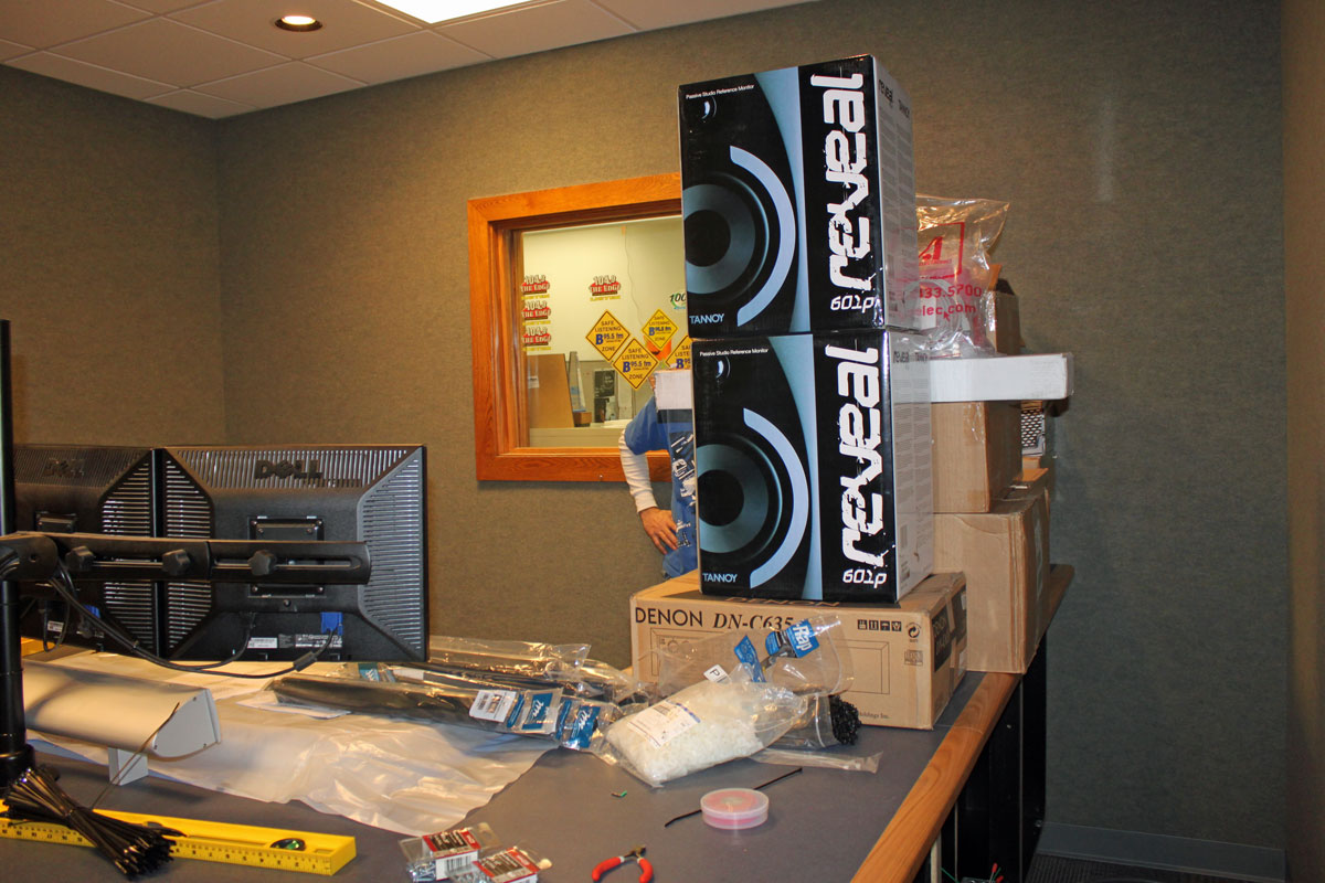
New studio equipment to be installed
For monitors, we are using the Tanoy 602p near field monitor placed on the table top above the computer screens. This studio will not have a turret. Turrets used to be necessary to hold things like cart machines and CD players. These days the CD players are used so infrequently that it was decided to put them in the side rack under the counter top. Turrets also take up a lot of counter top space that can be put to better use.
New studio punch blocks
Punch blocks and power connections. The red outlets are isolated ground UPS type, the back outlets are feed by the emergency generator power panel. All electric wiring is inside of the metal conduit. The punch blocks are the inputs to the SAS RIO link unit, one 16-pair analog audio cable and ten category 5e shielded cables. The cat 5e is used for computer and TDM data buss to the router.
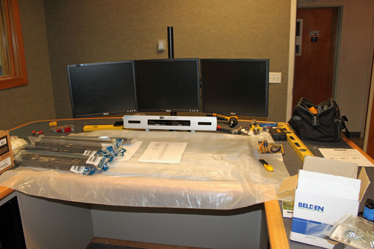
New Studio Rubicon console
The SAS Rubicon console is cut into the counter top and protected by plastic sheets.
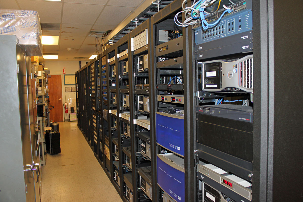
Rack room
Rack room with 32KD routers. This facility has 9 studios total plus a news room with three work areas.
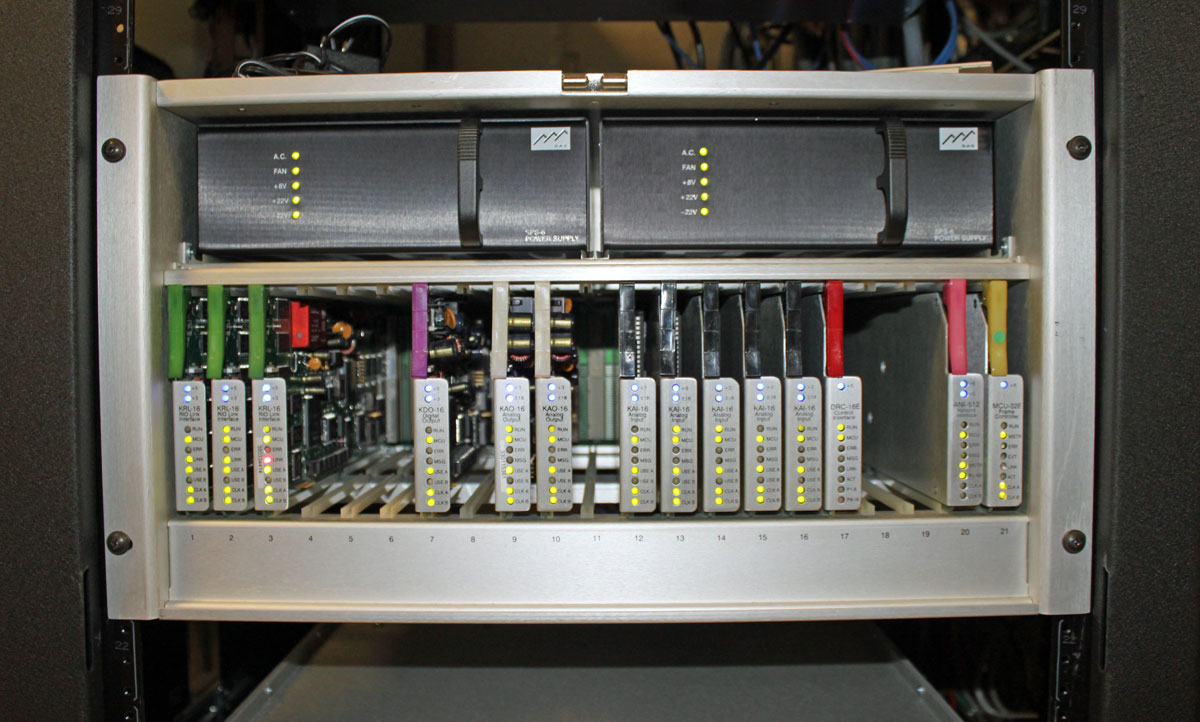
SAS 32KD router on line
The SAS 32KD router. All audio from the automation systems, satellite feeds and other sources is connected directly to these units. This unit is on line for other studios that have already been converted to the SAS gear.
FM and AM broadcast radio processing has gone through many iterations. At first, the main processing function was to limit the input audio to a transmitter and prevent over-modulation. This was a particular problem with early tube-type AM transmitters, where over-modulation could create power supply overloads and kill the carrier while engineers scrambled around resetting things and hopefully pressing various buttons to get the transmitter back on the air.
Over the years, processors incorporated not just limiting, but compression, gating, equalization, clipping, and so on all in an effort to keep ahead or at least abreast of the station across town.
Today, broadcast air chain processors come in all shapes and flavors. In addition to that, internet streaming stations have their own unique set of issues to deal with. The top-of-the-line Telos Omina or Orban Optomod systems are great, however, they can set one back a pretty large sum of money. Enter then, the Stereo Tool PC based software processing program.
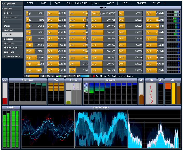
Stereo Tool sofware screen shot
The first difference between, say the Omina and Stereo Tool is the end user decides the hardware and basic operating system. The second difference is Stereo Tool comes with a free trial. Then there is the price difference, which ranges from about $48.00 US for the basic version, to $161.00 US for the basic FM version and finally $269.00 US for the full version (actual prices are in Euros, which will fluctuate day to day and the credit card company will likely charge an exchange fee). Add to that a medium-speed (2 Ghz) Intel Pentium4 or better computer, 1 Gb or more of RAM, good sound card and it all comes out to a reasonably priced audio processor.
Here are some of the specific features for broadcasting:
The idea of PC-based audio processing is new and interesting to most of us. The designer and owner of Stereo Tool, Hans van Zutphen, was nice enough to answer a few questions I posed to him via email:
PT: What prompted you to write audio processing software?
HvZ: Since I was very little I’ve always wanted to have my own radio station. I remember playing with walkie-talkies and trying to receive their sound on a real radio when I was about 8 or 9. I never really did anything with it until I found out in 2001 that you could easily start a webradio station – I actually found out because I was listening to a pirate station in my car which turned out to have a stream; within a week my own station was online.
Of course, I needed a bit of processing for it, and I wrote some command line tools – a single band compressor, a stereo-to-mono converter that didn’t cause any loss of audio (I was broadcasting hard trance on a mono 56 kbit/s stream, and this was the only way to get a decent sound out of it), and sometime later a multiband compressor.
In 2004 I left the company I worked for (ASML, they make machines to make computer chips, customers are companies like Intel, AMD etc.) to start working for Philips Healthcare, where I was going to work on image processing for X-Ray systems. I had 2 months of ‘spare time’ between those jobs, and I wanted to learn to program in Visual C++, so I decided to a GUI around my command line tools, and make a Winamp plugin out of it. I called it ‘Radio Tool’. I never really planned to do anything with it, it was just an exercise project.
About a year later I came across the Winamp site again and I saw that you could upload plugins. So I uploaded my program, now renamed to ‘Stereo Tool’ because a Google search for “Radio Tool” gave far too many hits. Within a week there were over 1000 downloads and a while later it surpassed 90,000. At that point I decided to create a new version, Stereo Tool 2.0.
For quite a while this remained a hobby project, I occasionally worked on it for a few months and then I wouldn’t look at it for months. But at some point I was approached by someone people who worked at a “real” (FM) Dutch radio stations who asked for some extra features – he couldn’t get the audio loud enough, and that’s how I got into clipping. Things started to get better, I learned more and more about processing, the number of downloads increased and people became more and more enthusiastic about it. At some point, after reading something about how an FM stereo signal looks, I thought it might be possible to output a stereo signal with a 192 kHz sound card, so I bought one and did some tests and it worked that same night, and within a few weeks I added RDS.
PT: Do you know, approximately, how many stations (AM/FM/internet) Stereo Tool is being used on?
HvZ: FM: About 500, ranging from small community and pirate stations up to large nation-wide stations which run Stereo Tool at a dozen transmitter sites. Streaming: Not sure, but definitely over 1,000, probably a lot more.
PT: I have read through the forums on your site, Stereo Tool looks like a very complete processing system. Any plans for new features, future upgrades, etc?
HvZ: Yes. I’m currently working on a new multiband compressor. The multiband compressor in Stereo Tool is still based on the code that I wrote in 2001 for my webradio station, which in turn was based on an even older version that I had used on 8-bit audio. It also has far too many bands. Because of this, the multiband compressor is currently the weak spot of Stereo Tool. In the last weeks, I have made a new single-band compressor that sounds a lot better, it actually outperforms other compressors I have tested, and I expect great results for the new multiband compressor, which will also have fewer bands. Something else that I’ve been planning for a long time is a composite clipper, which will add 1-2 dB of extra loudness and especially better highs. Stereo Tool can already be louder with good audio quality than nearly any hardware box on the market (see for example this video, Radio 538 uses an Orban 8600 http://www.youtube.com/watch?v=4VpfcqUPQys – unfortunately due to the mpeg compression it’s a bit difficult to compare but listen for distortion ) – but there’s always room for improvement.
PT: What are the advantages of a PC software-based processor vs. a hardware-based (e.g. Omni or Optomod)?
HvZ: Ah, good question. Not sure if it’s the right question… With processing, a lot of things come down to taste, and there are several stations that have replaced their hardware processing with Stereo Tool not because it’s software and PC based but because they preferred the audio that comes out of it. Stereo Tool is also one of only 2 processors that contain a de clipper (the other one is the Omnia 9, I licensed my de clipper to them). For a demo of the declipper see: http://www.youtube.com/watch?v=oqOljvx9KaM
Also, Stereo Tool contains a stereo and RDS coder, but most other processors don’t, so instead of having a whole bunch of devices everything can be done in a single PC, which also results in better quality. Recently I added a new feature that enables synchronizing multiple FM transmitter signals that all connect to a simple Shoutcast stream (video: http://www.youtube.com/watch?v=GYQ5CYs0ZX8 ), so you also don’t need any streaming hardware anymore.
Of course, there’s the price. A hardware box that gives “similar” quality (of course every processor sounds different, and it’s a matter of taste, so it’s difficult to compare, but I’m assuming that things like low volume levels, gain riding, distortion, and lack of clarity in the highs are bad) easily costs $10,000 or more. And you can always easily upgrade to new versions. If you already have a PC with enough spare processing power you don’t need to buy anything.
I know that some people at radio stations are ‘afraid’ of using a PC in their processing path, but based on feedback I get from the stations that run my software it’s completely stable – and of course, if a PC does break, you can replace it with any fast enough PC you have lying around – you just need to put the proper sound card in.
But for development, the advantages are huge. If you use DSPs, it’s usually a lot of work to even make a very small change. When I worked at Philips Healthcare, the image processing that had been done – without many changes – on DSPs for many years was being converted to PCs because of the speed of development and the price of hardware. Once the conversion was finished, the development speed increased dramatically and 2 years later the image quality had improved beyond anything that was imaginable with DSPs. PCs get faster every year, and you don’t have to do anything for that – for the same price the processing power that you can buy roughly doubles every 1.5 years, and if you pay more you can get even more. If you use DSPs, you have to do a lot of work yourself, you cannot just ‘buy a faster DSP’. Testing things is very easy, I can write some code that does something new, post it on my forum and I’ll have feedback from users the next morning – with DSP that’s a LOT more difficult and it takes a lot more time. I’ve learned by now that everyone hears things in a different way, and occasionally there are groups of people who hear something they find very annoying while many other people (often including myself) don’t hear anything wrong with it at all. Especially in cases like this, it’s really great to be able to quickly send new versions to several people all around the world for testing.
PT: Are there any particular sound cards that work better with Stereo Tool?
HvZ: Yes. For the best results, use the Marian Trace Alpha, with the ESI Juli@ as the second-best choice (it needs calibration).
Thank you very much, Hans, for the interesting insight.
Check out the videos, especially the de clipper video, which is quite amazing. That will clean up all but the most ham-handed DJ mistakes.
PC-based audio processing software is a great solution station on a limited budget that cannot afford high-end air chain processors. There are many LPFM’s, Part 15 stations, and others that can get great-sounding audio and RDS for a very reasonable price. Currently, the AM settings do not allow asymmetrical modulation, which is more of a US thing. There is some talk of adding it in a later update.
It is surprising to me how many times I have seen this done incorrectly in the field. Summing a stereo source, whether it is balanced or unbalanced is not simply twisting a couple of wires together. This will effectively reduce the impedance of the outputs by one-half. With newer, active balanced outputs, this may cause damage to the output amplifiers.
The parallel resistance formula is thus:
Therefore a 600-ohm stereo output tied together would look like this:
Rt = 1/(1/600+1/600) or 300 ohms.
It also creates an impedance mismatch with the next piece of gear, which will affect the common mode noise rejection of the circuit.
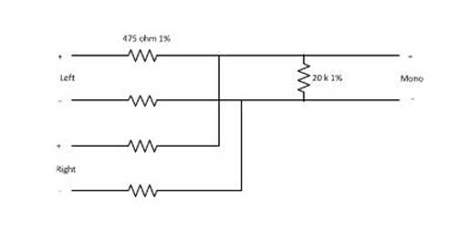
The best way to sum is through a resistive network. That way stereo separation is maintained, the impedance of the output circuits is maintained and the output amplifier will not current cycle. That looks like this:
resistive summing network
Pretty easy to fabricate in the field. It is good to do things the right way, it sounds better on the air too.
We are starting to work at a new client’s studios. It is a bit like stepping into a 1980s time machine, as the newest console seems to be the Broadcast Audio console in the FM studio. I feel I should wear a wide colorful tie and part my hair in the middle when working there. There is also an older UMC console in the second production room.
A what?
Exactly.
It seems the UMC console (UMC was a Connecticut-based console manufacturer that was later sold to Broadcast Audio) was having an intermittent hum problem on all the audio buses.
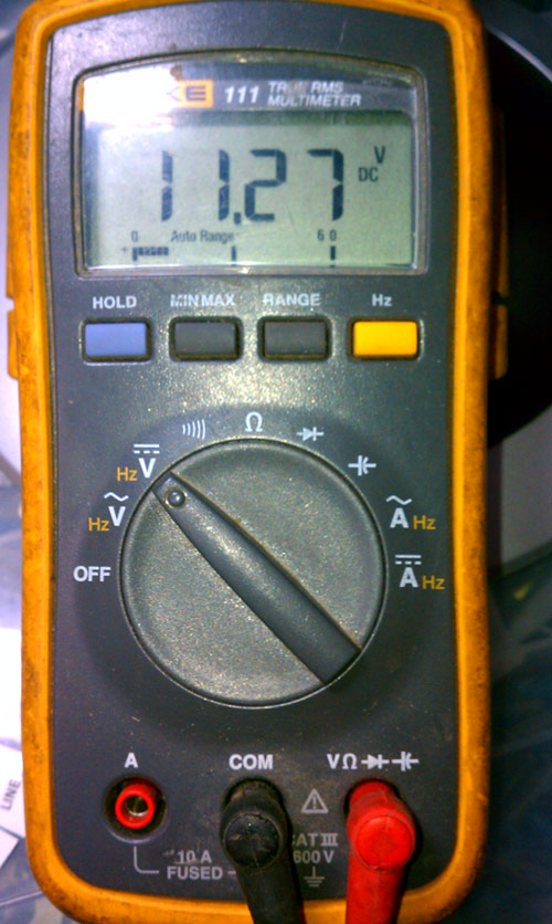
After poking around under the hood for a few minutes, I decided I should begin with the basics. Checking the power supply for ripple seemed like as good a place to start as any. This console has a 30-volt and a 12-volt power supply. The 30-volt supply checked out good, but the 12-volt supply, not so much:
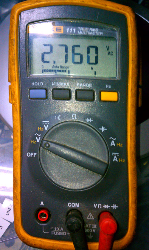
12 volts DC, 2.7 volts AC12 Volt power supply
2.7 volts AC on the 12-volt DC power supply. That will put some hum on the audio, all right. I tried to replace the power supply main filter capacitor, but it had no effect. The regulator must also be bad and it is a Motorola part number which is likely not made anymore.
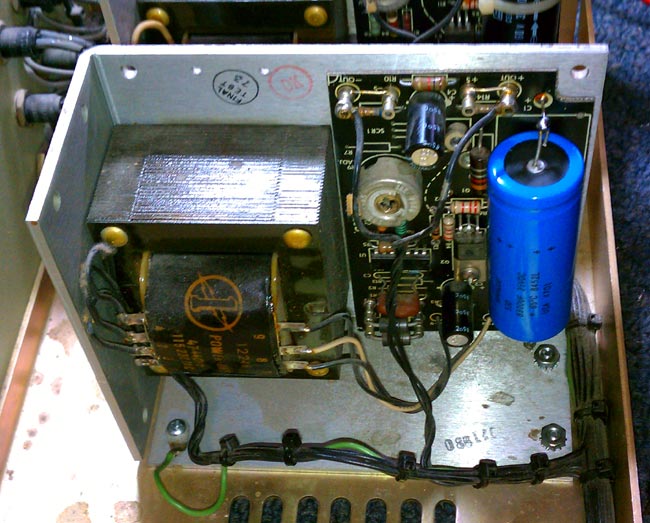
12 volt linear power supply
This is a pretty standard off the shelf power supply, I should be able to get one from Mouser for about $60.00 or so for a linear unit, which will be cheaper than us trying to trouble shoot and repair the old one. In the meantime, I took the 10 amp 0-30 volt bench supply and pressed it into temporary service. The console is working again, for now.
At some point, all this old, um, stuff needs to be replaced.