This has nothing to do with broadcasting. It does, however, have a good deal of geeky goodness.
I have started a new project, getting on the air on the 630 meter Amateur band. For those who do not know, 630 meters is from 472–479 kHz which is below the AM (or Standard) broadcast band. It was formerly part of the Maritime Mobile allocation. For US Amateurs, these frequencies were added in 2017 so it is a relatively new experience.
There is no commercially available equipment for this band, so it depends on the potential operator to make his or her own equipment which is where the fun begins.
To start, I thought I’d repurpose a WSPR beacon to 630 meters to do some antenna experimentation. Like all transmitters, the output of this unit needs to be filtered to reduce or eliminate out of band emissions. The Amateur radio service falls under Part 97, which has somewhat different requirements than Part 73 or 74.
47CFR 97.307(d) states:
For transmitters installed after January 1, 2003, the mean power of any spurious emission from a station transmitter or external RF power amplifier transmitting on a frequency below 30 MHz must be at least 43 dB below the mean power of the fundamental emission.
That is a fairly low bar. I am going to shoot for something better. WSPR beacons center around 475.6 kHz. The harmonics are at 951, 1428, 1902, 2378, 2853, 3329, 3804, 4280 and 4756 KHz. The first two are in the AM broadcast band. A quick look at the Zachtek WSPR beacon show these harmonics:
unfiltered ZackTek WSPR Desktop transmitter, 630 meter band
Definitely does not meet the out of band emissions standard set forth in FCC 97.307. Typical of solid state amplifiers, the odd harmonics are greater than the even.
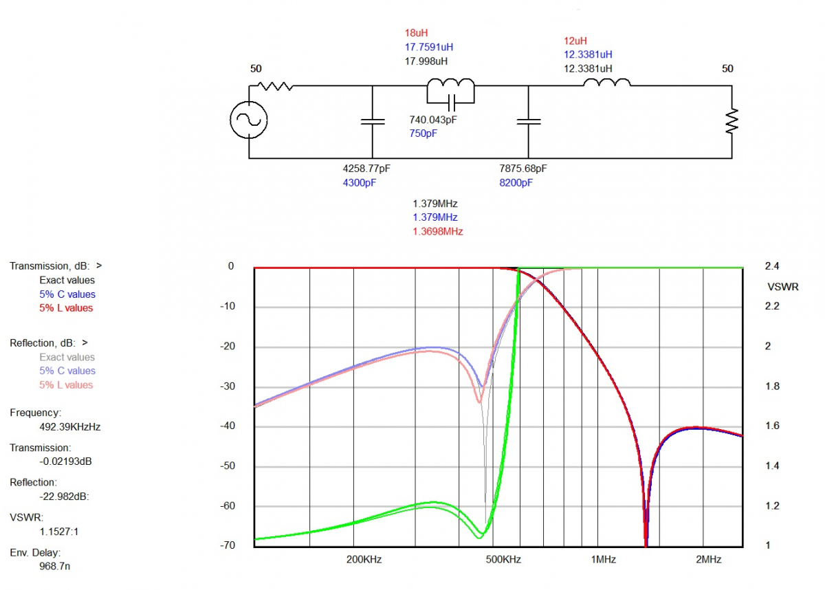
I used a filter design program called Elsie to design suitable filters for 630 Meters. There are two types of filters that can attenuate the harmonics; low pass and band pass. A low pass filter passes all emissions below the cutoff.
630 Meter low pass filter
That is fine, however, it does not eliminate the possibility of interference and inter- modulation from frequencies below the band. Both types of filters are also good for receivers in the presence of AM broadcast band towers, which can desensitize receiver front ends when located nearby.
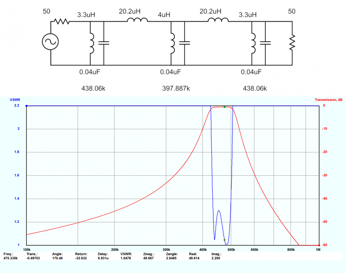
A band pass filter cuts off frequencies above and below the pass band.
630 Meter band pass filter
This is a nodal inductor-coupled band pass filter. I like this design because it has deep shoulders and has better performance with the harmonics in the AM broadcast band.
Prototype low pass filter:
630 Meter Low Pass Filter
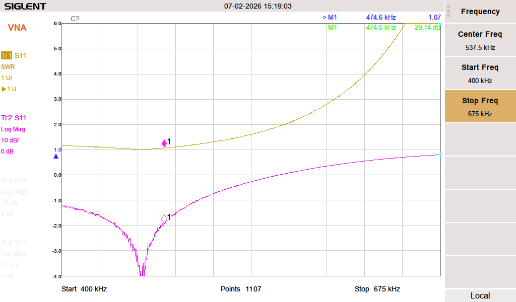
Quick prototype board. Capacitors are Cornell Dubilier silver mica dipped, the inductors are wound on T130-3 material. The SWR and return loss:
Smith chart:
The Smith chart shows that it is slightly inductive on the desired frequency. The way to mitigate is to either add some capacitance (not easy) or reduce the inductance (somewhat easier). I tried tuning it by changing the spacing on the windings of L1 and L2. There was no change.
Low pass filter response:
The second harmonic on 951 KHz is -58.37 dBc. Harmonics 3 – 7 are 40 dB below the fundamental. This is adequate but the band pass filter below is better.
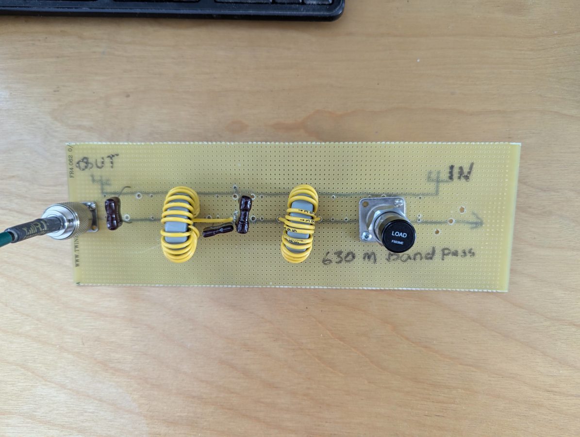
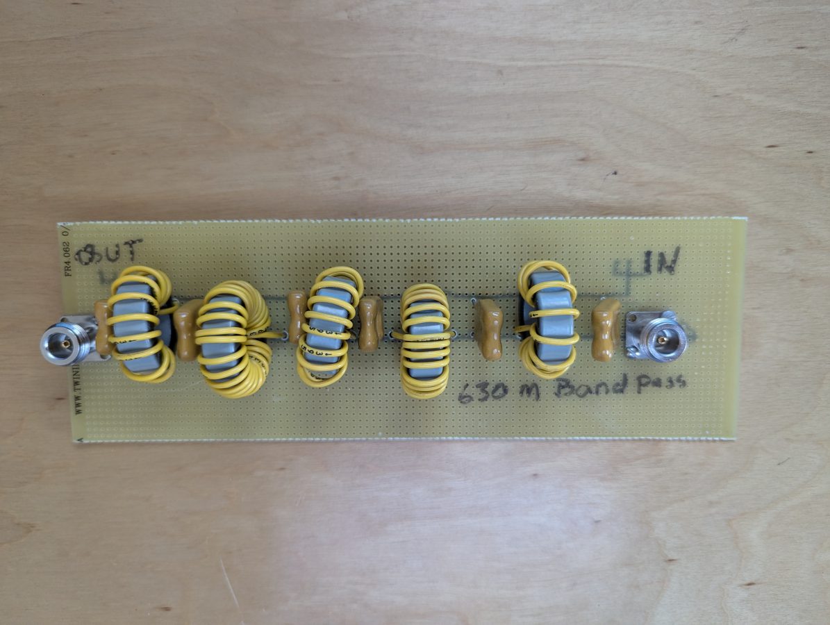
Prototype band pass filter:
630 Meter band pass filter prototype
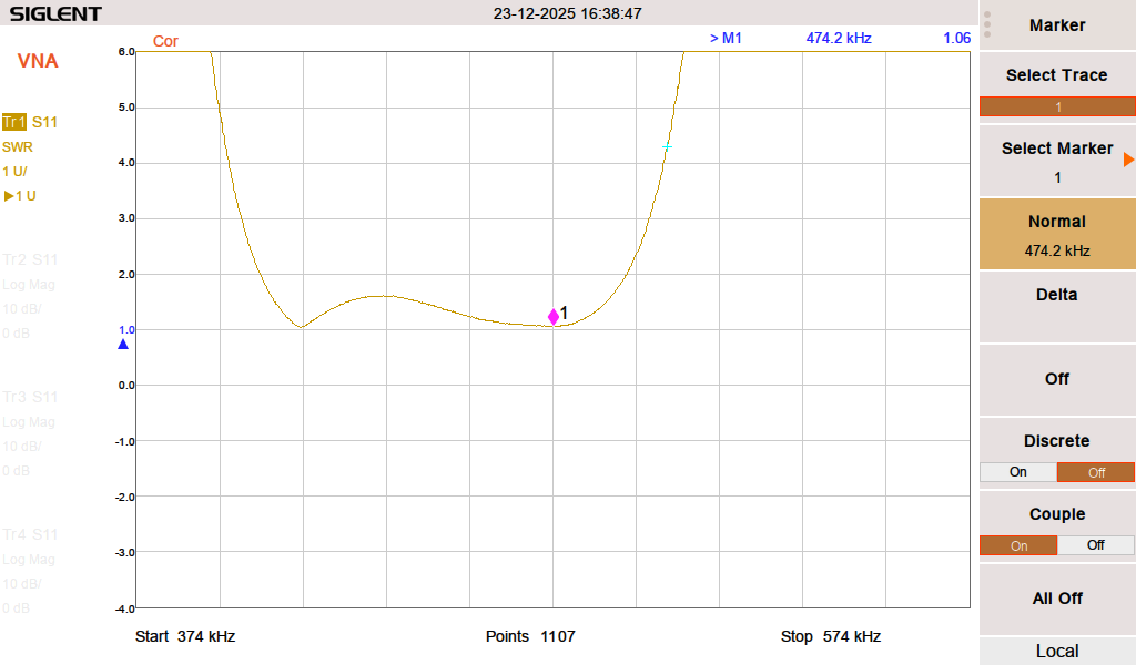
The above filter is a little rough, but it was a good test of the filter program’s design parameters. The capacitors are Cornell Dubilier 0.02 uF 500V. The inductors are wound on T130-3 iron powder toroid cores. The results are good:
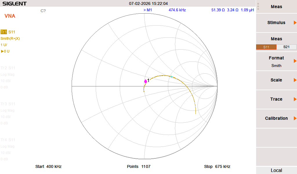
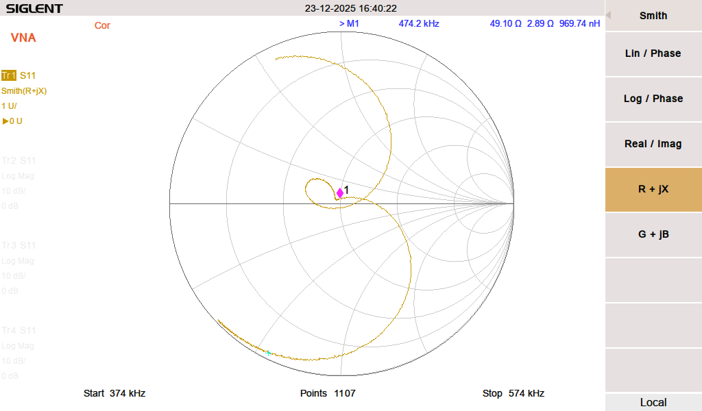
630 Meter band pass smith chart
By adjusting the spacing of the windings on L3 (center of the board), I can tune the VSWR and Return loss for best values.
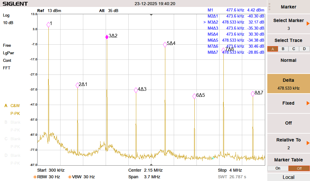
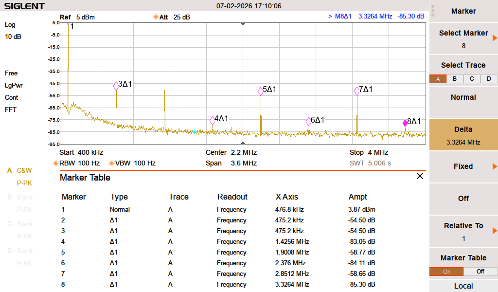
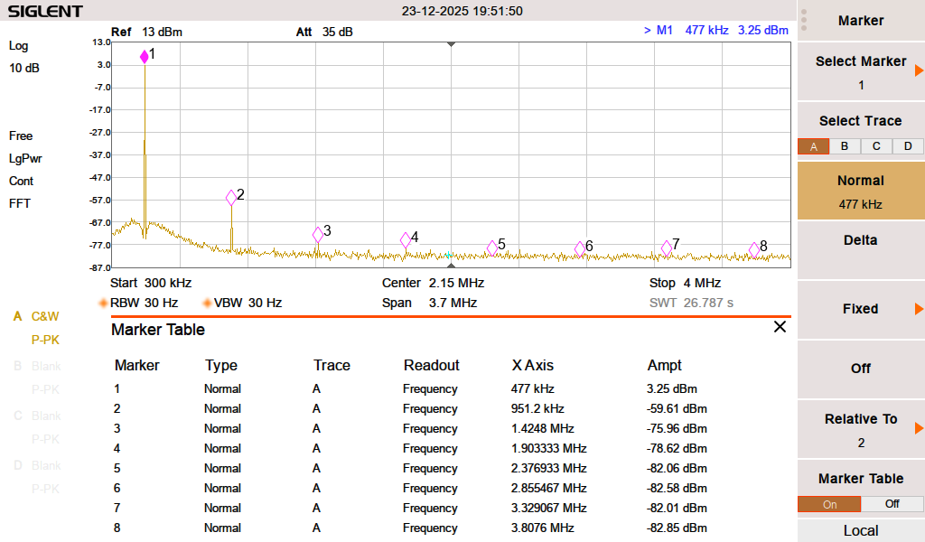
The same ZachTek WSPR transmitter noted above, running through the prototype filter:
ZachTek 630 Meter band pass filter response
The second harmonic on 951 KHz is -62.86 dBc. The rest of the harmonics are less than that.
Of the two, the band pass filter has better performance characteristics. The return loss/SWR is lower and can be tuned by adjusting the spacing of the toroid windings on L3.
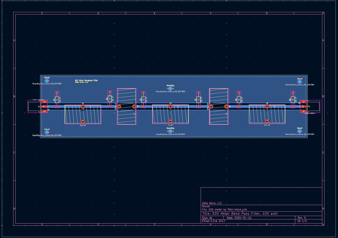
I decided to take the next step and make a PCB. I have KiCad on my Linux machine, which works well. Sometimes some of the foot prints need to be edited so the dimensions are correct, but that is easy.
KiCad design 630 meter band pass filter
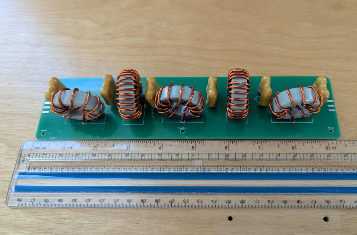
What I like about this board design is that it will work on any amateur band below 7 MHz with different component values. I had five boards fabricated and built one of them out. The T130-3 toroids are wound with 14 AWG magnet wire. The capacitors are same used in the prototype, 0.02 uF, 500V mica dipped.
Cleaned up band pass filter board
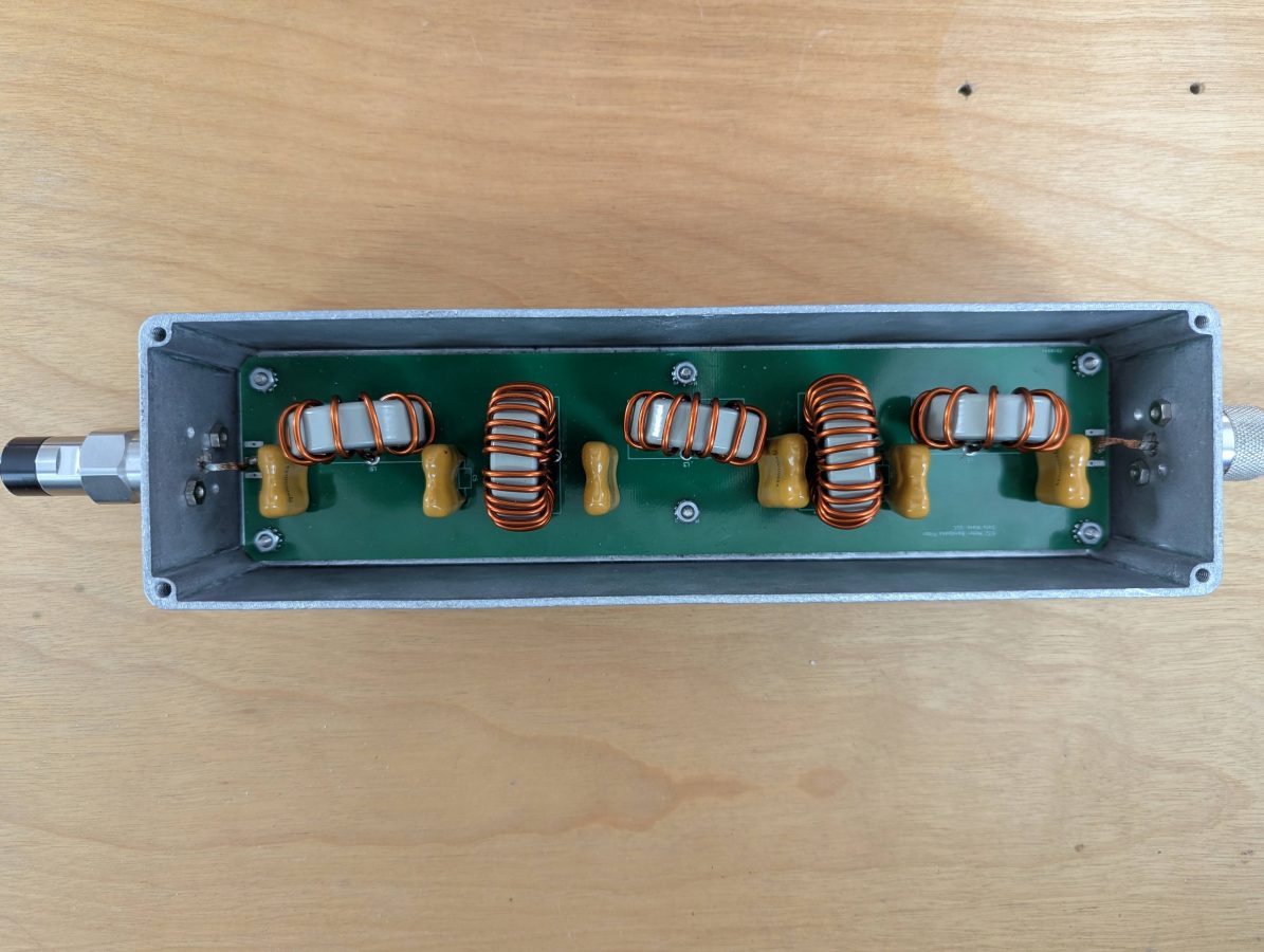
Board mounted in aluminum enclosure:
Band pass filter mounted in diecast aluminum enclosure
This build has similar measurements to the prototype board above. Based on what I found while making this, I made a few tweaks to the circuit board in KiCad. I would consider selling these, if there is enough interest.
The antennas are the most interesting aspect of Radio Frequency Engineering to me. The transfer of power in the form of voltage and current to the magnetosphere and back again is where the rubber meets the road. Any opportunity to experiment with the art of antenna design and fabrication is welcome.
This is for the Amateur Radio community. With the upswing of Solar Cycle 25, predicted to peak in July of 2025, I decided it would be fun to get back on the air with some type of HF setup.
My past experience with HF radio and peak solar cycles is that wild fluctuations can occur creating band openings at unusually high frequencies or no propagation at all. The geek in me finds this very interesting. HF Propagation is a complex matter. Long-distance communication can be carried out with very low power levels provided the ionosphere is bouncing signals back to the earth instead of absorbing them.
Weak Signal Propagation Reporter (WSPR) is an HF beacon system, where stations transmit a digital signal containing your call sign and Maidenhead Gird locator for several seconds. The challenge is to have an efficient antenna and use as little power as possible. In this case about 200 mW (0.2 watts) or 23 dBm. The modulation type is MFSK and the bandwidth is 6 Hz. According to Wikipedia, which is mostly accurate about things like this; WSPR uses a transmission protocol called MEPT_JT. That sends messages composed of:
28 bits for callsign, 15 bits for locator, 7 bits for power level, total: 50 bits.
Forward error correction (FEC): non-recursive convolutional code with constraint length K = 32, rate r = 1⁄2.
Number of binary channel symbols: nsym = (50 + K − 1) × 2 = 162.
Keying Rate is 12000 ⁄ 8192 = 1.4648 baud.
Modulation is continuous phase 4 FSK, with 1.4648 Hz tone separation.
Occupied bandwidth is about 6 Hz.
Synchronization is via a 162-bit pseudo-random sync vector.
Each channel symbol conveys one sync bit (LSB) and one data bit (MSB).
Duration of transmission is 162 × 8192 ⁄ 12000 = 110.6 s.
Transmissions nominally start one second into an even UTC minute: e.g., at hh:00:01, hh:02:01, etc.
Minimum S/N for reception is around –34 dB on the WSJT scale (2500 Hz reference bandwidth).
Distant stations report reception to a database. Several good websites display reception in a map or table format.
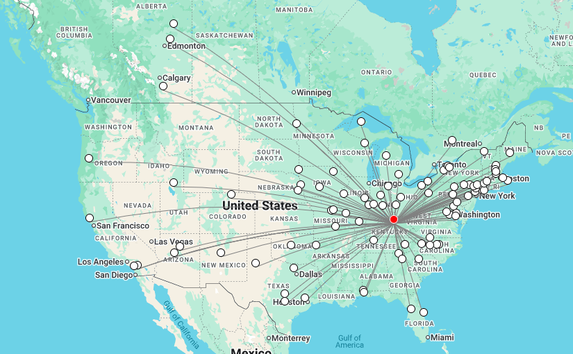
WSPR report
This map shows a good path to coastal Maine on 40 meters. The received signal-to-noise ratio is -2 dB at a distance of 423 KM.
80 Meter End Fed Half Wave antenna supported by trees
My antenna is an End Fed Half Wave (EFHW) cut to 3.568 MHz which can be used on any harmonically related frequency (7, 10, 14, 18, 21, 24, and 28 MHz). To accomplish this, a 49:1 Unun (Unbalanced feed to unbalanced feed) transformer is used to transform the 2,400-ohm impedance of the wire to the 50-ohm impedance required by the transmitter. The antenna works best against a ground system that is not less than 0.05 wavelength or 18 electrical degrees on its lowest frequency. That works out to about 4.2 meters (14 feet). A little bit longer is a little bit better. Six 20-foot long 14 gauge bare copper ground radials are attached to an 8-foot ground rod.
Diecast aluminum box containing 49:1 Unun
The Unun is two FT240-52 (not an affiliate link) cores with 14 gauge enamel wire consisting of 2 turns on the primary and 14 turns on the secondary. The antenna is 40 meters (132 feet) of 10 gauge hard-drawn stranded copper wire. This should be good for about 800 watts CW/SSB on HF if I want to use it in that capacity.
Unun transformerUnun wire tied to a DIN rail with 100 pF 5 KV capacitor
There are several guides on how to make the unun available via Google search. There is some debate on whether a 64:1 transformer should be used. Most indicate a 49:1 is the best match. The diecast aluminum (not an affiliate link) enclosure is a nice feature. It cost $33.00 on Amazon.
I used the network analyzer to trim up the antenna a bit. I made a few measurements, the first was just the wire with no ground connected. The next was the wire and ground system after trimming the length for resonance on 3.5 MHz.
The transmission line is LMR-400 with N connectors. I loath PL-259s and use N connectors whenever possible.
I did a series of broadband SWR sweeps. The first was just the wire prior to trimming.
First sweep, frequencies are a little low, SWR is a little high
The next was with a ground rod and six ground radials, #14 bare copper wire twenty feet long.
EFHW trimmed up and looks good on everything except 60 Meters (10 MHz)
This demonstrates the effect of a good ground system. It is worth the effort (and it is an effort) to put in some buried ground radials with this type of antenna. I think above-ground radials would work too.
Here is a screenshot of the little Zachtek desktop WSPR beacon transmitter I bought. This is a great addition to the toolbox and works well for testing the radiation efficiency of an HF antenna. It has a GPS antenna input for timing and location reference. The frequency bands are selectable if you are testing a mono-band antenna. It will work into a fairly poor load, so I suggest sweeping the antenna first with an analyzer.
Zachtek configuration web interfaceWSPR beacon, 0.2 watts
This shows that my signal is getting out. So far, the furthest distance is 17,030 km with an SNR of -10 (Australia, VK5ARG). That is quite amazing when you think about it. I am letting this run overnight to see how the propagation changes. Overall, this was a good recreational project and now I have a known working HF antenna.
One small RF project that I am working on; a 770 KHz notch filter. I always figure if I am having this problem, then others may be having it too. This is a relatively simple idea, a resonant LC circuit (AKA a tank circuit) tuned to the carrier frequency. It should have a bandwidth of +/- 15 KHz of the design frequency. Another requirement; use the parts I have available. Finally, the environment in which this is to be used is a high-noise room; with lots of computers, LED lights, etc therefore it needs to have excellent RF shielding.
Something like this would work well for anyone that lives around an AM transmitter site and is having problems with receiver sensitivity or transmitter intermodulation.
The basic design looks like this:
Parallel LC tank circuit
Time for a trip to the local storage facility known as “The Barn.” In my backyard, there is a small agricultural structure that is used for storage of just about everything. In The Barn, I found several parts salvaged from an old Energy Onyx Pulsar AM transmitter. As such, they are more than capable of receiver operation and could likely handle a fair amount of RF power in the transmit mode.
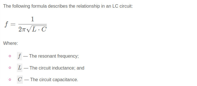
CDM F2B 0.01 uF capacitor with back of N connector inputs
Finding a type F2B 0.01 uF capacitor, rated at 2000 volts and 11 amps, the value of the inductor was calculated. For the inductor, a 20 uH coil with taps will work great. For receive-only applications, much smaller-sized components can be chosen. Also, there are many bandstop filters with multiple poles. Those are great, but I like the simplicity of the parallel resonant LC circuit.
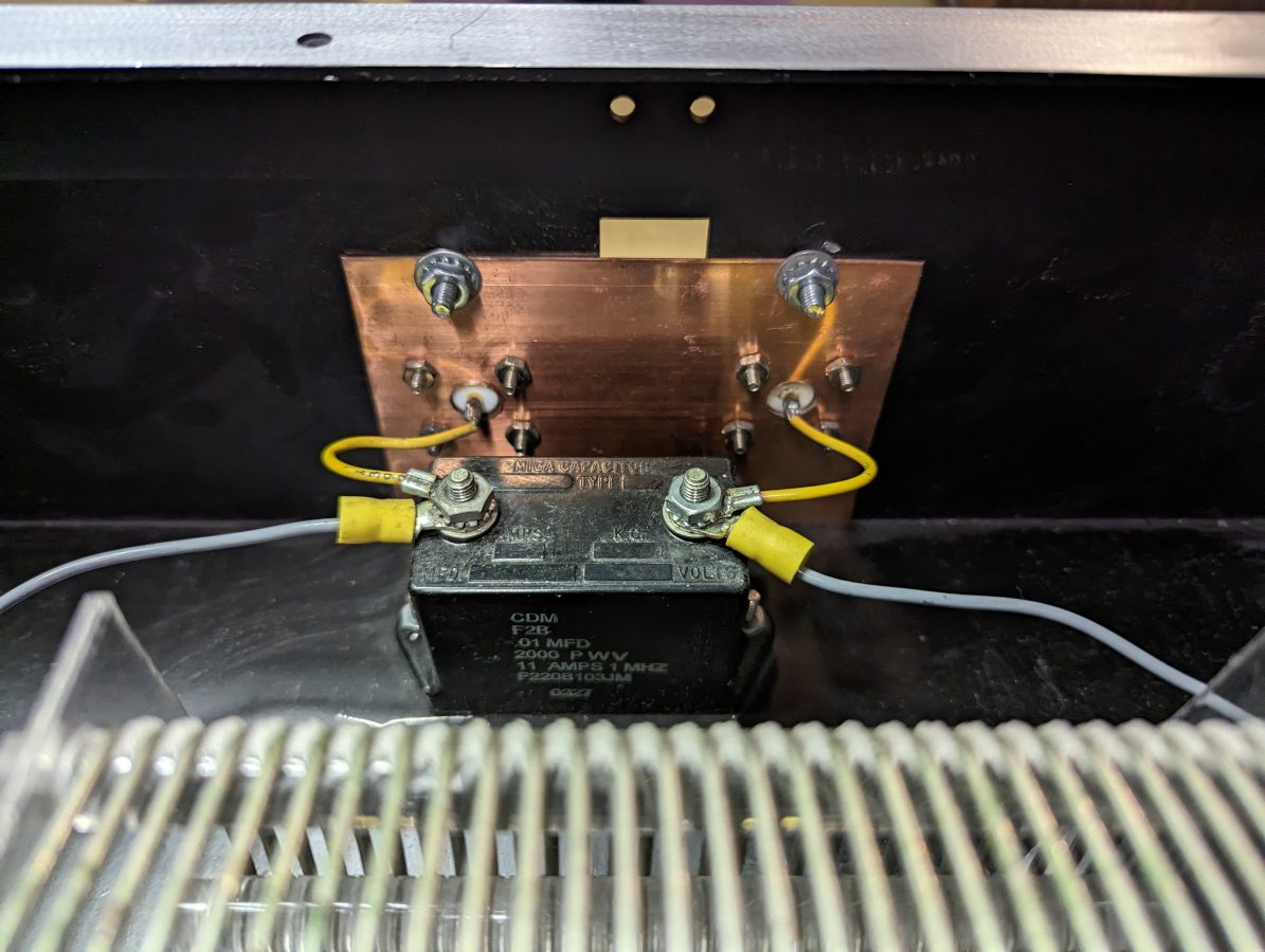
20 uH inductor salvaged from Energy Onyx transmitter
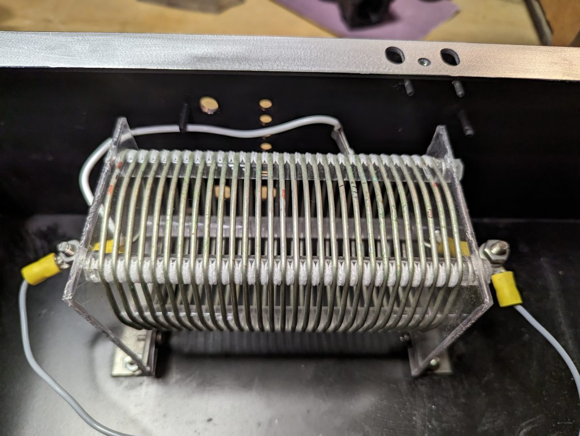
The N connectors were salvaged from I don’t know where and the enclosure used to house a power supply for a Radio Systems console.
N connectors for input and output.
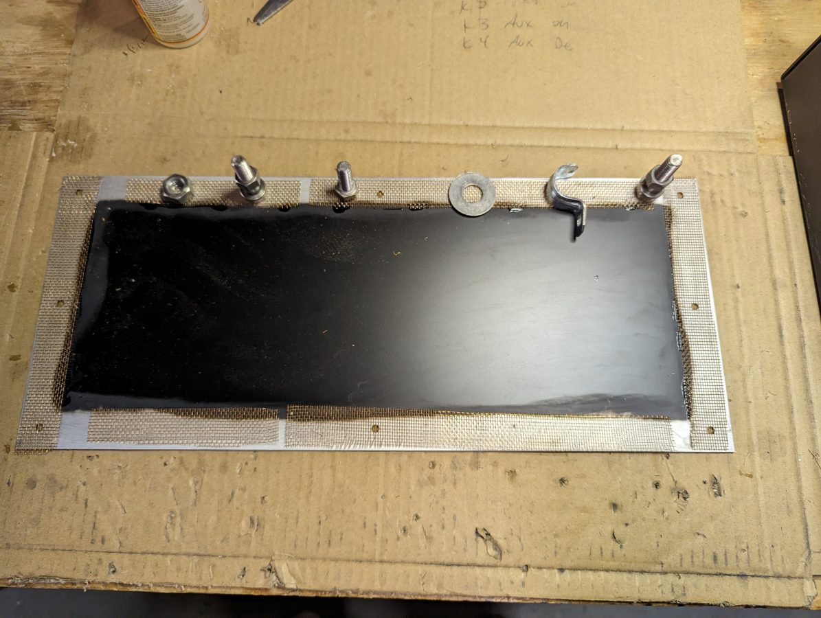
For shielding, I sanded the paint off of the enclosure where the lid is attached and tacked some brass screen down with gorilla glue. This will make a good RF contact surface. The outer of the N connectors are bonded to a piece of copper ground strap which also has a grounding lug on it.
Enclosure lid with brass screen to make contact
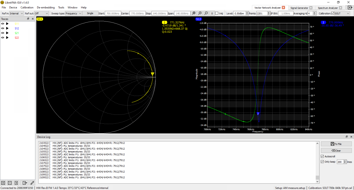
I used the Libra VNA to tune it up:
S12 shows return loss, S21 shows Phase
The scan shows it is -31 dB on the carrier frequency. It is -17 dB on 760 KHz and -20 dB on 780 KHz. This is good, because I may still want to listen to the station on the remote receiver. According to the smith chart, it is actually resonant on 771.5 KHz, but that is close enough for this application. I think the resonance went up slightly when I put the cover on after the tune-up.
There are several tank circuit calculators online. It is best to have more capacitance and less inductance to keep the Q of the circuit low and suppress the sidebands as well as the carrier.
Before anyone ever thought to click a mouse and play the latest Ke$ha “song,” or spin Stairway to Heaven for the millionth time, radio was used for a different purpose. Early radio was developed to transmit messages between ship and shore or between continents. Radio apparatus consisted of spark gap transmitters, which were very simple devices only suitable for sending Morse code. Some did experiment with voice modulation methods, but the quality was poor. It was not until Lee Deforest developed the vacuum tube that the state of electronics art was capable of transmitting voice and music.
ATT developed AM (amplitude modulation) for point to point long distance service over high-frequency radio circuits. This is how early intercontinental long-distance phone service was first established. In fact, up until the early 1970s much of the long-distance telephone traffic was routed via high-frequency stations like WOO, WOM, and KMI to Europe and Asia. It was this development that allowed Ham Radio operators to begin transmitting music and other programming to their neighbors and the idea of broadcasting was born.
The Coastal Radio stations that for years transmitted and received messages from ships and sea, transmitted navigation warnings, weather broadcasts, news, and responded to distress calls have all but faded away. The operators of those stations often become nostalgic with the memory of sitting in a small room late at night straining to hear what might be a faint SOS call under all the other chirping CW notes. Successfully “working” a distress call is considered the pinnacle of a shore operator’s career. High-Frequency Continuous Wave (HF CW)(Continuous Wave is the technical description of Morse code modulation) has several distinct advantages for distress work. A small signal can travel long distances and still be well received. The average lifeboat CW transmitter had 5-watt output and often they could be heard across an ocean, 1,000 miles away.
I put together a few lists of these Coastal (ship-to-shore) radio stations. The first is commercial public stations, these were responsible for sending message traffic to and from ships at sea. They often had other purposes like transmitting signals point to point or High Seas Telephone service. High Seas Telephone is just the way it sounds, persons on board a vessel at sea could place a telephone call. It was hugely expensive and was replaced by INMARSAT, which is only moderately expensive.
Call Sign
Location
Owner
Services
Notes
KFS
Palo Alto, CA
Federal Telegraph/ITT
Coastal
Sold to globe wireless, ceased operation 7/12/1999
KPH, KET (point to point)
Pt. Reyes, CA
RCA/MCI
Coastal, point to point
Sold to globe wireless ceased operation 7/1/1997
KLB
Seattle, WA
ShipComm, LLC
Coastal
In service
KMI
Dixon, CA
ATT
Coastal, High seas phone service
Ceased operation 10/8/1999
KSM
Pt. Reyes, CA
MRHS
Coastal
In service
WBL
Buffalo, NY
RCA
Coastal (Great Lakes)
Ceased operation 1984
WNU
Slidell, LA
Coastal
Sold to globe wireless ceased operation 7/12/1999
WLC
Rogers City, MI
United States Steel
Coastal (Great Lakes)
Ceased operation 1997
WCC
Chathem, MA
RCA/MCI
Coastal
Sold to globe wireless ceased operation 1997
WLO
Mobile, AL
ShipComm, LLC
Coastal, (oil rigs)
In service
WOO, WDT (point to point)
Toms River/Ocean Gate, NJ
ATT
Coastal, High Seas and point to point
Ceased operation 10/8/1999
WOM
Pennsuco, FL
ATT
Coastal, high seas phone service
Ceased operation 10/8/1999
WSC
Tuckerton, NJ
RCA/MCI
Coastal
Ceased operation 1978
WSL
Brentwood, Sayville, Southhampton, Amagansett, NY
Federal Telegraph/ITT
Coastal, point to point
Ceased operation 1984
This is by no means an inclusive list as at one time there were hundreds of these stations licensed to the US. There were many inland stations on the Great Lakes and rivers. These are the most common ones that I’ve heard, heard of and or seen personally.
KPH
Most people mark the end of commercial Morse Code as July 13, 1999. There is, however, one station, KSM, which still is open as a public coastal station. That station is a part of the Maritime Radio Historical Society, which operates from the former KPH facilities in Pt. Reyes, California. KPH suspended operations in July, 1997 while other station continued on for the next two years.
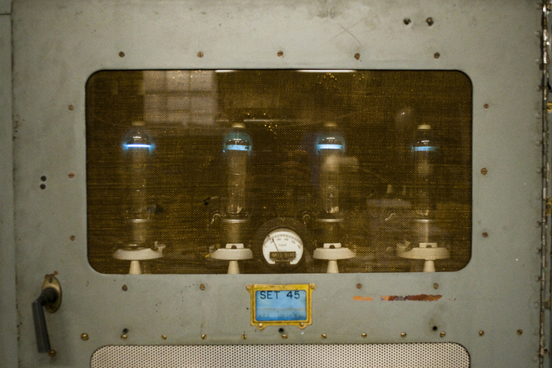
Mercury Vapor Rectifiers from PW-15 transmitter, courtesy of MRHS
Press Wireless was a company used by newspapers to transmit articles and pictures. They developed their own transmitters and operated point to point sites in Hicksville, NY and San Francisco, CA. A few of their transmitters survive today at KPH.
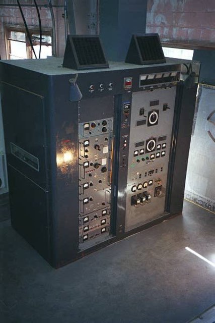
RCA H series HF transmitter, courtesy of MRHS
The 1950s H and K RCA HF transmitters were built to last. The carrier power is 10 KW and can be used for CW, SSB, and RTTY.
KPH is the best preserved Coastal Station, when the facility closed down in 1997, the US Park Service took ownership and left it mostly untouched. In 2004 volunteers and former station employees began to restore the equipment to operation. Eventually, these efforts led to the licensure of KSM, the only operating commercial CW station in the US. KSM uses restored donated equipment from KPH and KFS. Restoration work continues and if I lived closer, I’d volunteer my services. MRHS also operates amateur radio station K6KPH.
WOO
Other facilities survive in parts, the former WOO is home to the Tesla Radio Foundation and Museum. Anyone that knows anything about radio will recognize Tesla as one of the founding fathers, perhaps much more so than Marconi, who often gets more credit than is due. During it’s day, this was a huge facility, connecting North America with Europe, Africa, South America and Asia. Point to Point service included programming relays for the VOA, Long Distance phone service and so on.
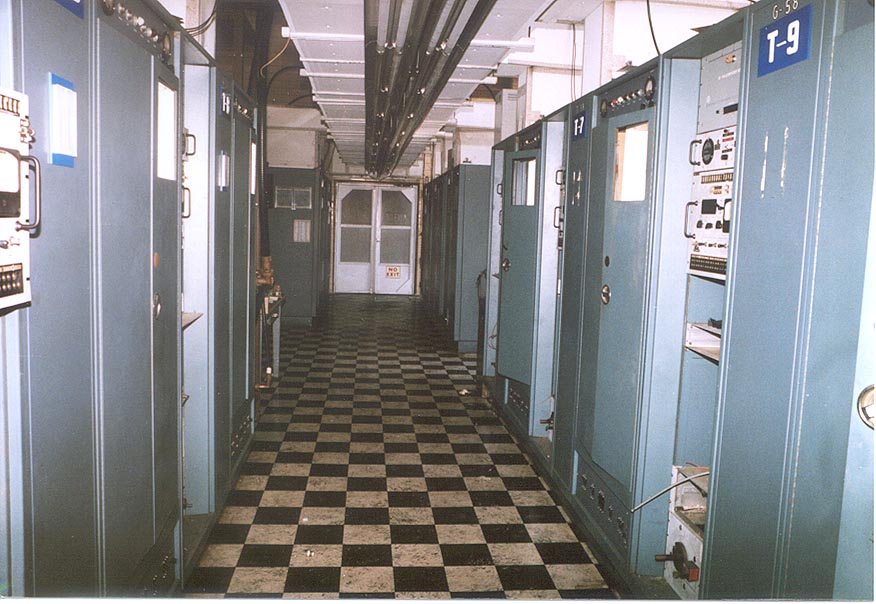
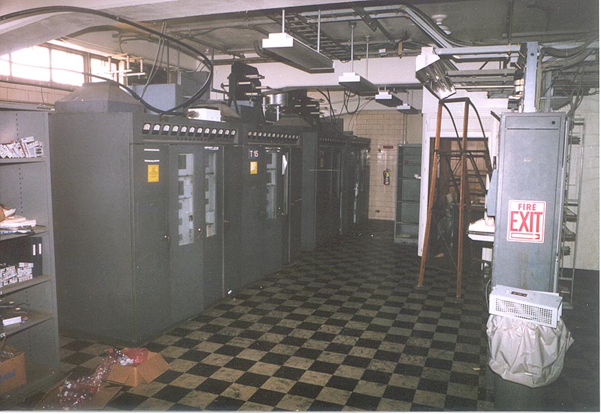
WOO transmitter floor, courtesy of Tesla Foundation
ATT seemed to use the same design for their HF sites, the buildings at KMI, WOO and WOM all look alike, right down to the brown/yellow tile floors.
WOO (PW-15 ?) transmitter, courtesy of Tesla Foundation
Again, this facility was restored through the hard work of Radio Amateurs. Unfortunately, unlike KPH, the old CW transmitters where scavenged for parts and none where restorable.
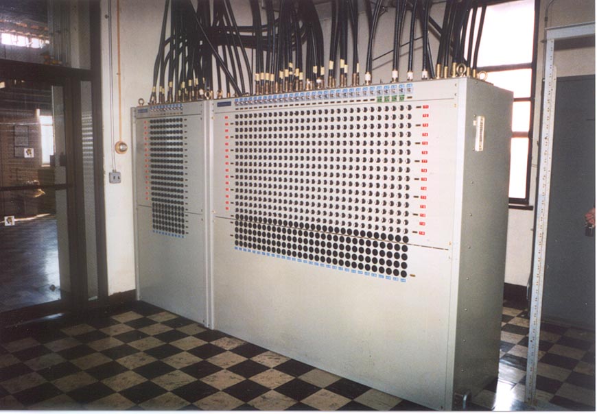
WOO antenna switching matrix
All of the transmitters were routed to this antenna switching matrix. As you can plainly see, there were many, many antennas at this facility. There were also several types, rhombics, verticals, inverted cones, etc. They were (some still are) located in a tidal swamp. From this matrix, with a few exceptions, the transmission lines were routed through BALUNs which then fed open wire transmission lines.
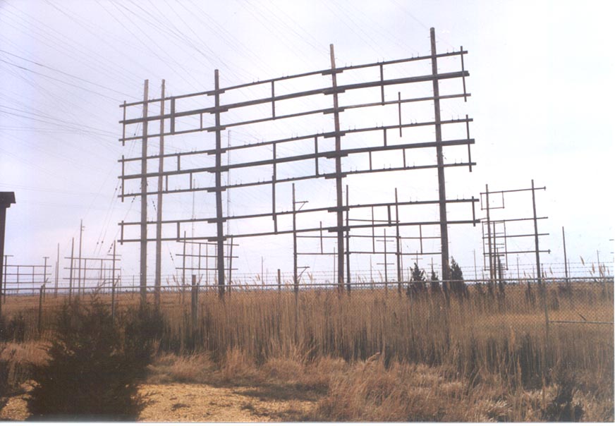
WOO Ocean Gate Radio transmission lines
These lines went to various antenna fields pointed at Europe, South America, Asia and Africa.
WCC
The former WCC receiver site is now home to the Chatham Marconi Maritime Center and has the amateur radio call sign WA1WCC. This is a museum that is open to public. The town of Chatham, with donations from Qualcomm and Verizon, has endeavoured rehabilitate the old receiver site and operations building. They have spent a fair sum of money on replacing plumbing, fixing the driveway and other necessary work to turn the site into a historical attraction and provide a center for Science, Technology, Engineering, and Mathematics (STEM) on Cape Cod.
WCC transmitting antenna, South Chatham, MA courtesy MHRS
We used to go to the public beach right next to this radio tower. It looks like a Milliken tower similar to WICC ‘s towers in Bridgeport. I believe the transmitter site in South Chatham was bulldozed and turned into a wild life refuge.
WLO and KLB are in service with HF voice and SITOR, PACTOR and AMTOR modes but not CW. These stations are operated by ShipCom, LLC.
Coast Guard Maritime Radio
The US Coast Guard operated a network of Coastal Radio stations as well. These where to communicate with Coast Guard vessels and aircraft but also interfaced with civilian shipping. They stretched up and down the east and west coasts, covered Alaska, Hawaii and territories like Puerto Rico and Guam. They ceased CW operations in 1995 and are remotely operated by the two surviving stations, NMC at Pt. Reyes and NMN in Portsmouth, VA.
Call Sign
Location
Services
CW close date
Disposition
NMA
Miami, FL
Limited Coastal, Military
1/4/1995
Remoted to NMN Portsmouth, VA
NMC
Pt. Reyes, CA
Limited Coastal, Military
1/4/1995
In service GMDSS
NMF
Boston, MA
Limited Coastal, Military
1/4/1995
Remoted to NMN, Portsmouth, VA
NMG
New Orleans, LA
Limited Coastal, Military
1/4/1995
Remoted to NMN, Portsmouth, VA
NMO
Honolulu, HI
Limited Coastal, Military, Point to Point
1/4/1995
Remoted to NMC, Pt. Reyes, CA
NMQ
Long Beach, CA
Limited Coastal, Military
1980
Closed
NMN
Portsmouth, VA
Limited Coastal, Military
1/4/1995
In service GMDSS
NMP
Chicago, IL
Limited Coastal, Military
1975
Closed
NMR
San Juan, PR
Limited Coastal, Military
1986
Closed
NOJ
Kodiak, AK
Coastal, Military, Point to point
1/4/1995
In service, GMDSS
NRT
Yokota, JP
Point to point
N/A
Closed 1992
NRV
Barrigada, GU
Coastal, Military, Point to point
1993
Remoted to NMO in 1992, then to NMC in 1995
This is by no means a complete list, there are several more stations that existed but were closed by the mid 1970’s.
GMDSS is the Global Maritime Distress and Safety System, an automated system consisting of satellites and HF radio that replaced the use of manned listening watches on ship and shore. A few years ago, the Coast Guard explored eliminating HFservices all together, however the public outcry was loud and vigorous, thus they didn’t carry through with the plan. Even so, the voice weather and navigation broadcasts are computer generated simulated human voices, which are not a good as the real thing, in this former operator’s humble opinion.
Unlike their civilian counterparts, most of these stations where disposed of without ceremony when they were turned off. Some former Coast Guard Radio Stations were sold off for land, others which were part of existing bases, were dismantled. The only exception to this is the remnant of NMY (New York) on fire island, now administered by the National Parks Service.
There are a fair number of former Coast Guard radio operators with fond memories of working at these places and the satisfaction of a job well done.
If you are interested in history, check out those sites and or pay them a visit if in the neighborhood. You may learn something you didn’t know before.