I want to explore all digital modulation methods for Standard Broadcast (AM, Medium Wave, or Medium Frequency). The most pressing technical problem for AM reception is electrical impulse noise. Can digital modulation solve this problem? Perhaps, but I am a natural-born skeptic.
To start out; I will say up front that the hybrid HD Radio (MA1) employed on AM was (or still is) a travesty. It never worked very well and it created massive interference +/- 20 KHz of the assigned frequency, especially when employed at night. Secondly; the all-digital version of HD Radio (HDMA3) remains a proprietary system with non-standard codecs. The current owner, Experi, has a license fee structure based on station type (AM, FM, LPFM, or Non-commercial) which ranges from $5,000 to $10,000 one-time fee for a five-year period. In all fairness; DRM pays a technology license fee to Fraunhofer for MPEG codecs used by receiver manufacturers and broadcast equipment. This is estimated to be between $0.13 to $1.13 US per receiver.
Those things being said, I thought a deep dive into the technical side of HDMA3 and DRM (Digital Radio Mondial) would be interesting. I did an article comparing MA3 and DRM a while ago: All Digital Medium Wave Transmission
What challenges are there to transmitting digital radio on MW? First, there is the very limited bandwidth of the channel itself. In North and South America, AM channels are spaced every 10 KHz (9 kHz in other places). On Medium Wave, the analog channel is +/- the carrier spacing, e.g. 20 KHz (or 18 KHz) with half of that channel potentially interfering with the adjacent channels. On a 20 kHz channel, this limits data transmission rates to 72 kbps or less with DRM and 40 kbps or less with HDMA3.
Secondly, skywave propagation is a potential difficulty for all digital broadcasts. Ionospheric changes can create multipath and fading, especially as the sun rises and sets causing the D layer to form or dissipate. Changes in the E and F layers can make or completely break skywave reception. Ground wave reception is reliable out to the limits of the noise floor, and varies based on transmitter frequency, power, and ground conductivity, and electrical noise in the area.
Everything that can potentially mitigate noise and skywave reception problems is a trade-off between robustness and data throughput.
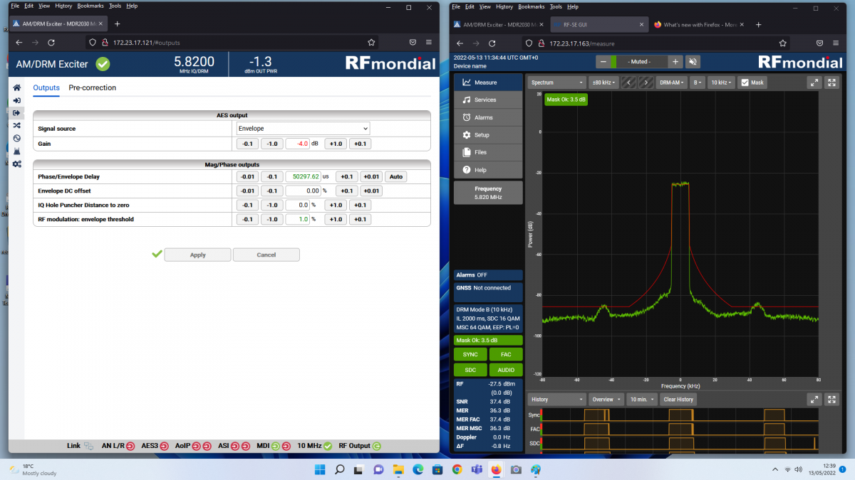
Screenshot of an HF DRM exciter from RF Mondial showing a 10 KHz wide channel on HF.
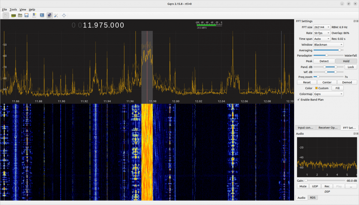
This is a screenshot of an SDR showing an HF DRM transmission received from a distance:
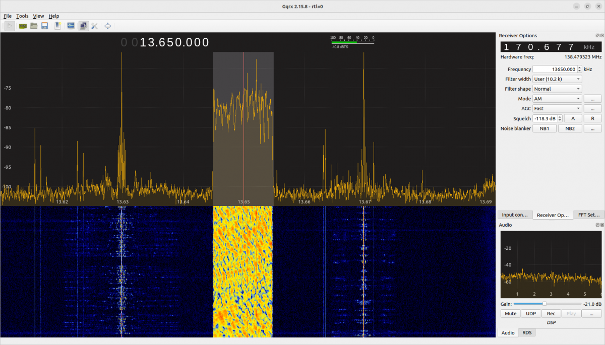
The receiver is not quite on bearing for this broadcast, however, it seems to be doing well. This is Radio Romania International’s Spanish broadcast targeting South America. The Pan Adaptor shows the signal is 10.2 kHz wide, but that doesn’t mean much from a $30.00 RTL SRD. The waterfall display below shows it is spectrally dense compared to the analog signals to the left and right. Note that with DRM there is no analog carrier being sent. Instead, a series of pilot tones are attached to various OFDM subcarriers for the receiver to lock onto.
A short Primer on COFDM
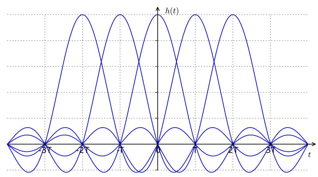
The modulation method for both systems is Coded Orthogonal Frequency Division Multiplexing (COFDM), which is the same system used by mobile phones, cable systems, WiFi (802.11), ATSC 3.0 TV, etc. COFDM consists of a group of subcarriers multiplexed onto one channel. The number of subcarriers and the subcarrier spacing relates directly to the data throughput and the robustness of the signal. OFDM is a very robust method that works well in the upper VHF, UHF, and SHF bands. It can work well in lower frequencies, however, there can be issues with multipath and Doppler effect. The coded part consists of forward error correction, which may include interleaving and subtracts from the data throughput.
The ability of an OFDM signal to reject electrical impulse noise, and deal with potential fading or multipath interference is based on a few things. The cyclic prefix sets the Guard Interval for the OFDM frame. The length of the Guard Interval should be the same as the multipath delay which helps mitigate inter-symbol interference and inter-subcarrier interference. Since the Medium Wave channels are fairly narrow, the number of OFDM carriers and spacing between carriers have a great effect on robustness. The fewer carriers the more robust the signal. This comes at the expense of data throughput; the fewer carriers the less data can be sent.
A short Primer on QAM
Each individual OFDM subcarrier is modulated with a Quadrature amplitude modulation (QAM) signal. The advantage of this is that each individual carrier sends data at a relatively slow rate and the aggregate data rate is the sum of all the subcarriers. QAM uses two carriers 90 degrees out of phase. The amplitude of each carrier determines the resultant vector of the modulated wave to create a data bit. For example; the sum of the carriers equals +45 degrees at 25% amplitude a 1101 data bit is sent.
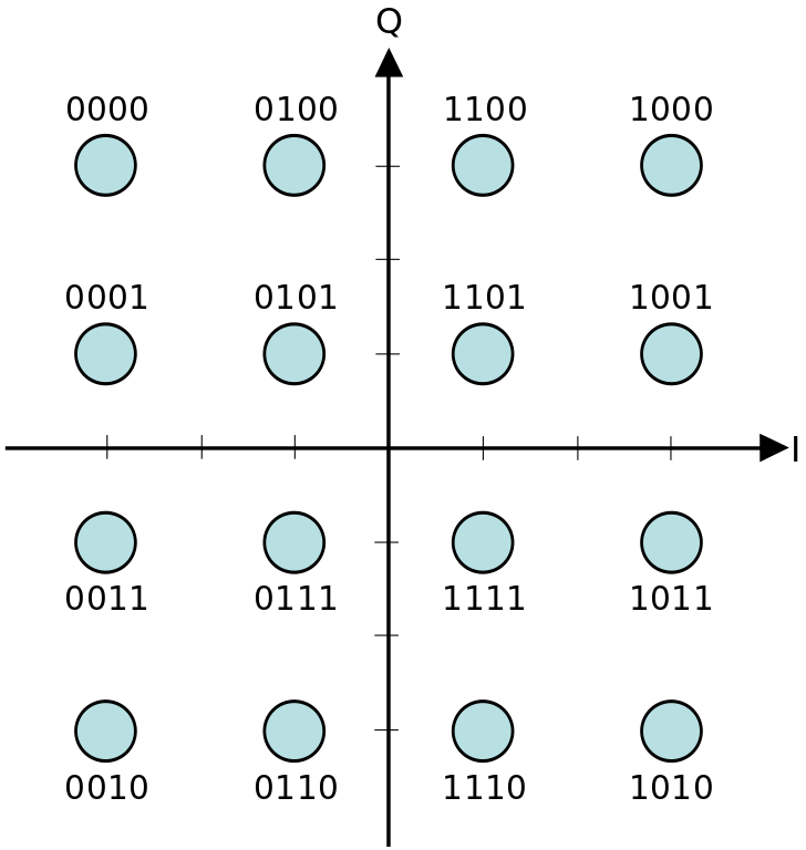
Both HDMA3 and DRM can use 16-QAM or 64-QAM. The larger the QAM constellation the more data can be sent. Smaller QAM constellations are more robust. HDMA3 can also transmit QPSK, which is Quadrature Phase Shift Keying. The resultant waveform from QPSK is identical to 4-QAM.
Bringing it all together
A DRM-modulated HF and MF transmitter uses both sidebands to transmit unique information. There is no carrier present but rather a few pilot frequencies for the receiver to lock onto.
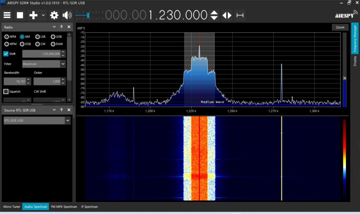
I like the waterfall display available with many SDR software programs. It gives a good indication of modulation density. With WFAS HDMA-3, the area +/- 5 KHz of the carrier signal has more power than the areas that are +/- 5 to 10 KHz from the carrier.
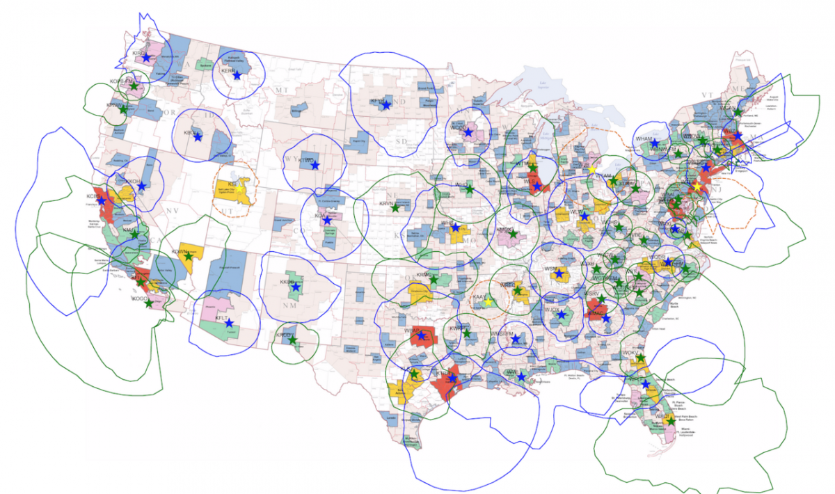
An HDMA3-modulated MW carrier sends the same data on upper and lower sidebands, effectively halving the data rate of DRM. There is a full carrier present, which represents approximately 25% of the transmitted power and does not contain any data. Currently, there are four three HDMA-3 stations transmitting in the US.
Both systems can make pre-corrections to the modulated signal in the exciter to compensate for amplifier non-linearities. This can greatly improve the MER and SNR.
The other perceived technical issue with AM radio is sound quality. This has to do mostly with poor-quality receivers, although there are some AM stations that are transmitting reduced-quality audio as well. There is a false notion that anything “digital” sounds better than analog. I would posit; it depends on several factors. Low-bit-rate audio codecs can sound abysmal. That being said, the newer high-efficiency audio codecs can sound quite good, but there are limits. With HD Radio, there is only one codec available; HDC+SBR. With DRM there are several; xHE-AAC, HE-AAC. xHE-AAC is designed to work with voice and can use bit rates as low as 12 kbps. It is possible for a robustly transmitted low-bit-rate codec to sound good with voice. It can sound okay with music, but not as good as analog FM.
Conclusion
Can an all-digital modulation format work well on the Standard Broadcast Band? The answer is; it’s complicated. One of the big positives of AM is that it is a very simple and well-tested system. Adding many layers of encoding and decoding is a violation of the KISS principle. That being said, using a digital modulation method that has been refined for mobile use over the years is a step in the right direction. There still is an issue with digital receivers; both HD and DRM. From what I have read, both formats are currently being included in several radio chip sets, yet I do not find those options in most car radios. There is a lack of public awareness, at least in the United States about digital radio in general. When someone says digital, most people think of streaming. When I am driving a rental car, I seldom find HD Radio, I do find Sirius/XM and all types of internet connectivity via smartphone apps.