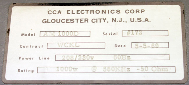
Originally signed on as WMNB in 1947, it is a Class C AM station on 1230 KHz, one of thousands in the country. Initially, it had a power of 250 watts, upgrading at various times to its current power of 1,000 watts.
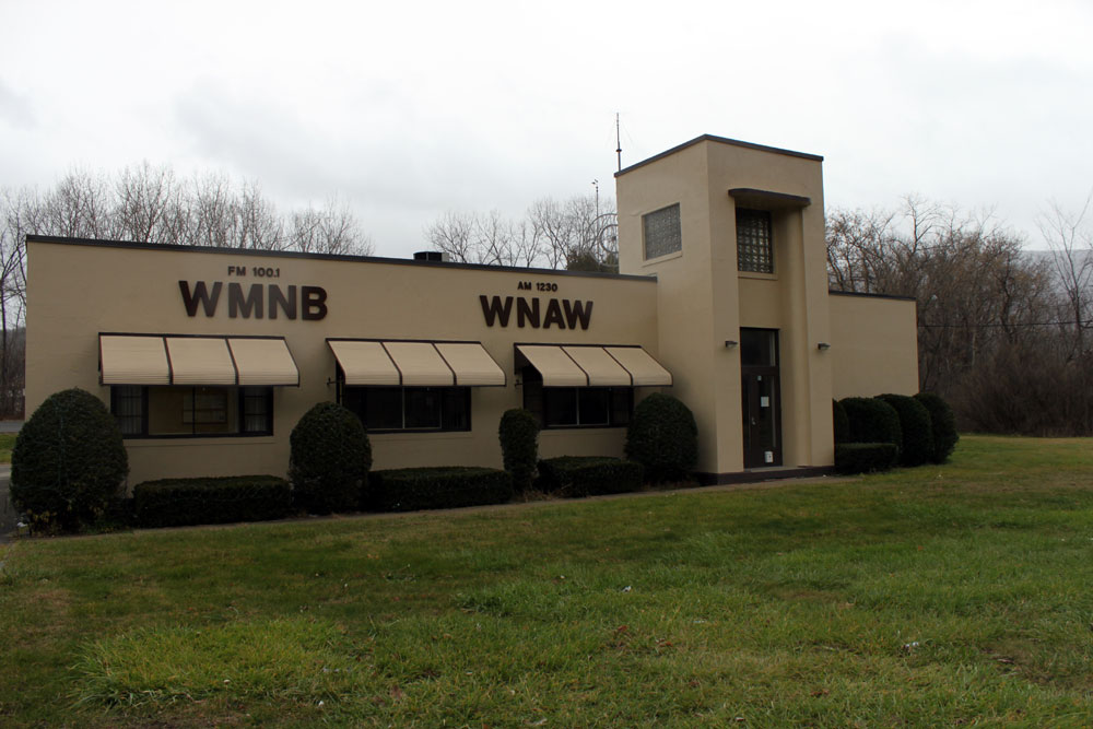
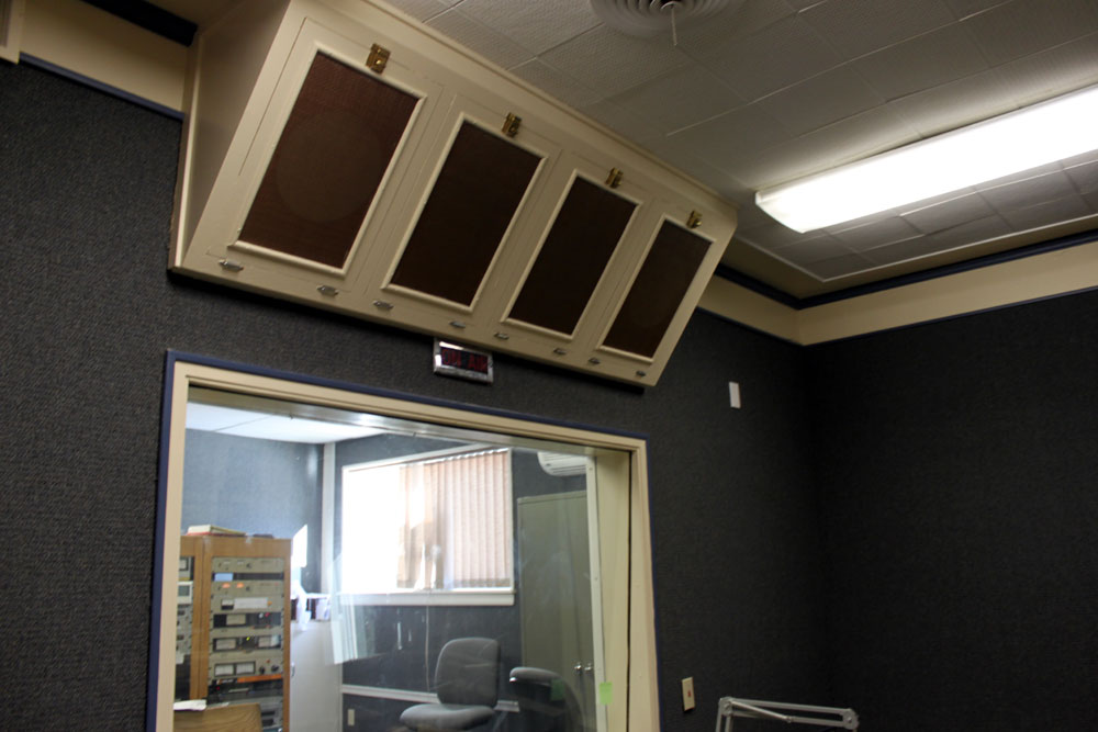
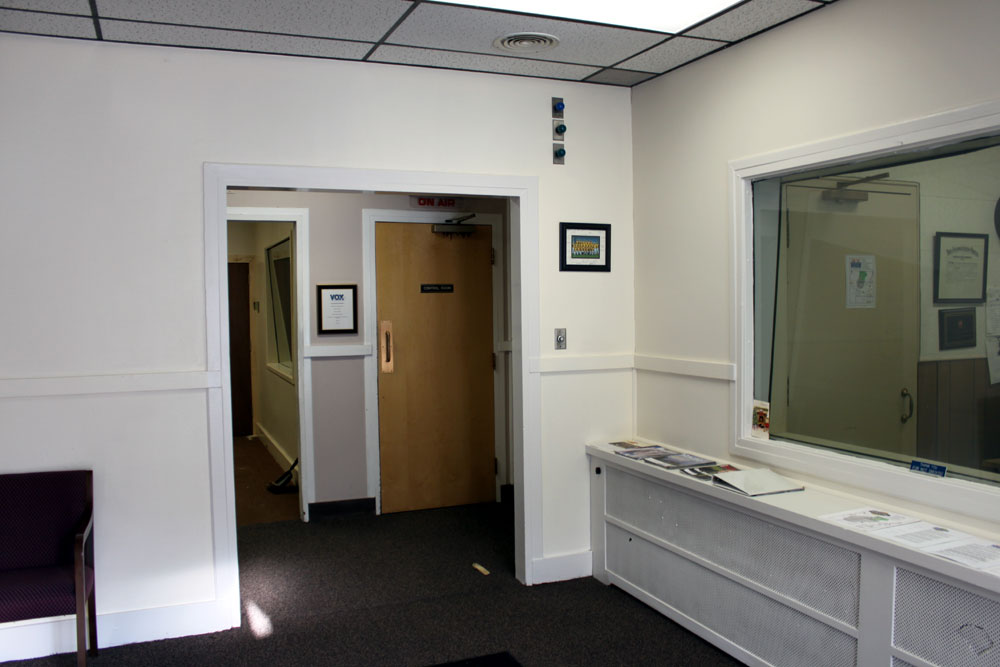
What is different about this station is the studio building. It is located in its original place on Curran Highway on the south side of North Adams. The studio is a late Art Deco design, complete with a small glass atrium in the lobby. Like many older radio stations, this installation was built on a raised floor. The walls and doors are all well constructed for maximum sound attenuation. The doors are large, heavy, and solid wood.
Inside, the original studios are laid out with a control room, a broadcast studio and a live performance room. At one time, the live performance room had a grand piano. Several times per week, live music shows were broadcast on the station. There was a large newsroom, and a big corner office for the General Manager and sales managers.
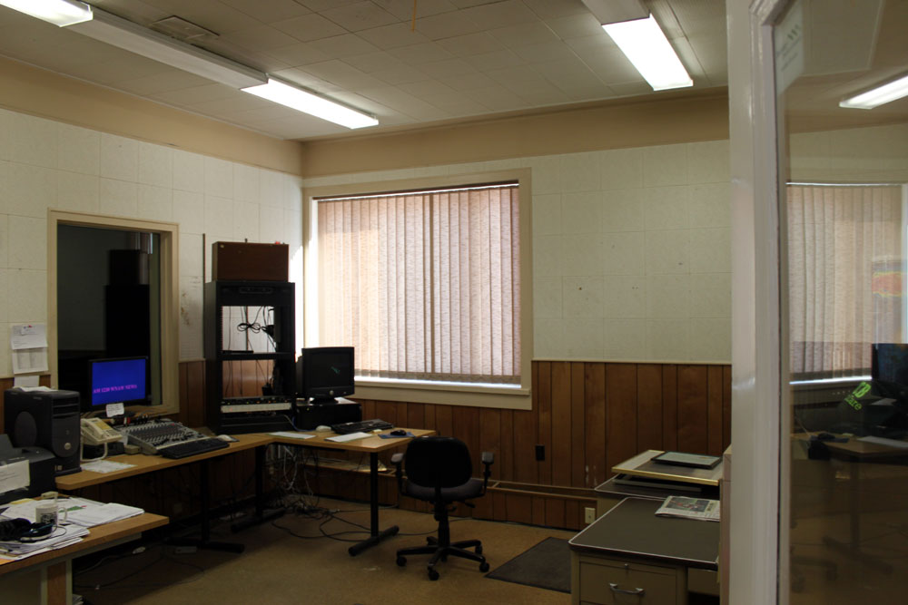
WNAW studio, looking into the control room. Back in the day, the announcer, whose only concern was announcing, worked in a separate studio from the engineer on duty, who worked console in the control room. The audio level limiting consisted of turning down the level on the console if the announcer started speaking loudly. They often communicated with each other with hand signs through the windows.
At the time that WMNB was signed on, the Adams/North Adams Massachusetts area was in the heart of the northeast manufacturing belt. Sprauge had a capacitor plant in Adams, GE was making plastics in Pittsfield, There were many textile mills still in operation and so on. The population was predominantly working middle class.
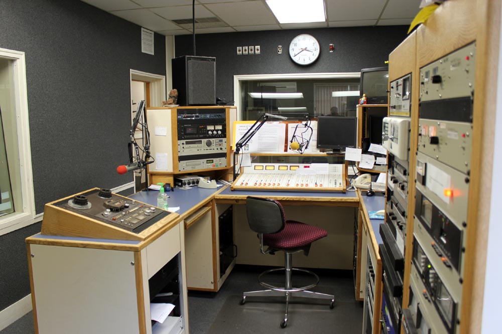
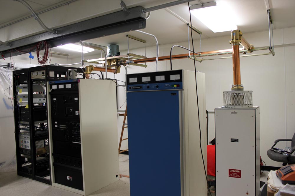
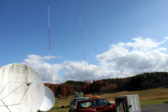
Obviously, the console has been changed since those days. The current console is a Audio Arts R-60. This serves as the control room for WNAW and WUPE-FM. The programming for WUPE-FM comes from Pittsfield on a T-1 line. From here, it is relayed to the transmitter site on a 950 MHz STL. WNAW transmitter is located about 2/10 of a mile south of the studio building on Curran Highway. It consists of a skirted self supporting tower with a Gates 1 solid state transmitter.
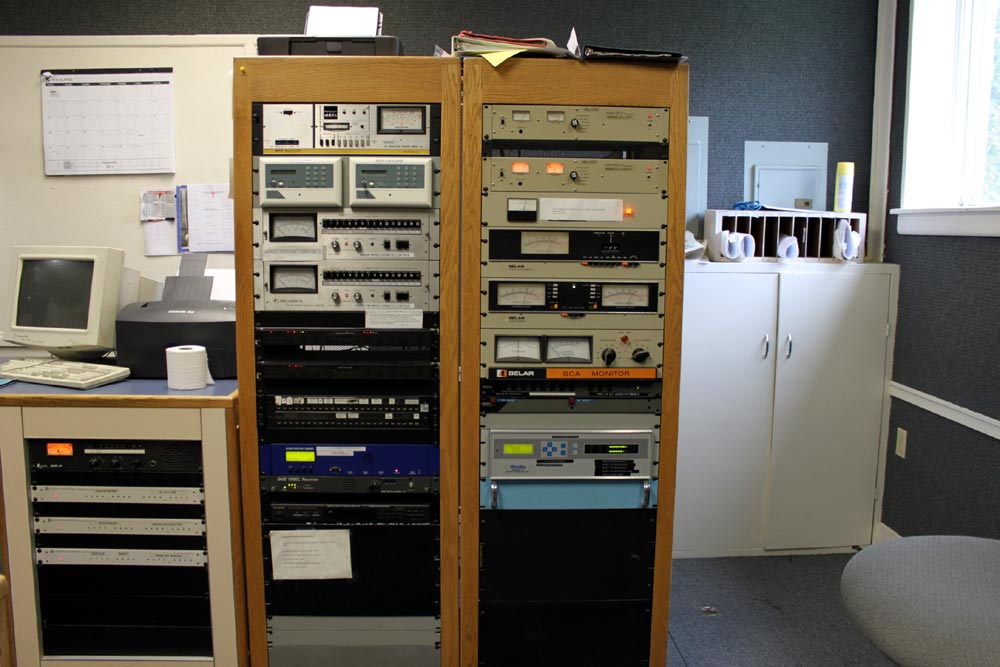
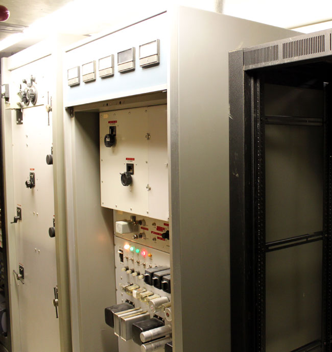
Equipment racks containing the T-1 equipment, modulation monitors and STLs. Note the very old Moseley TRC-15 remote controls. We have been unwiring these at the transmitter sites and disconnecting the TELCO lines. The transmitter sites now have Sine Systems dial up remote controls.
In 1961, WMNB-FM (now WUPE-FM) signed on the air from a tower north east of downtown, off of Mohawk Trail (MA route 2). It broadcast on 100.1 MHz with an ERP of 1,000 watts using a Gates FM1B transmitter.
WNAW continues on today as a community based radio station and is well liked and supported.