The Harris MW1A

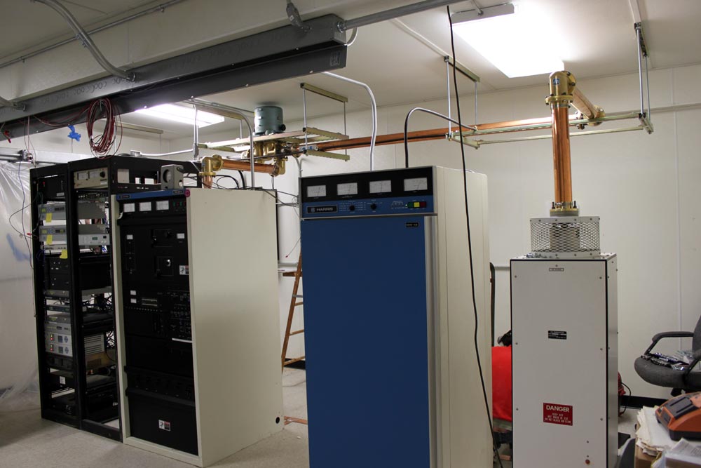
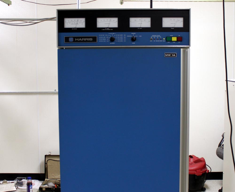
They say the first thirty years are the hardest, perhaps it is true. This Harris MW1A transmitter turns 31 this year:

Harris MW1A AM transmitter, WINE, Brookfield, CT

Truth be told, these are not bad units.  They have some quirks, however, the overall circuitry is simple, the design is simple enough and parts for repair are readily available.  They require regular infusions of RF transistors, but those are easy to change and are inexpensive to buy off the shelf from places like Mouser or Allied.

It is on the air as the main transmitter for WINE-AM in Brookfield, CT.   This is Harris’s first solid-state AM transmitter design, based on the work of Himmler Swanson.  This is not a PDM transmitter, rather, each module has RF transistors and audio transistors.  The output of all twelve modules is combined for a carrier output of 1,000 watts with +125% modulation.   Harris calls this PSM (Progressive Series Modulation), which is sort of high-level modulation.

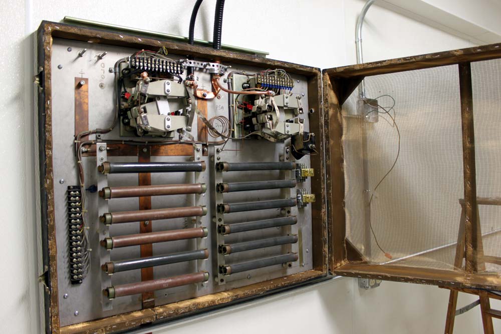
This is also the only transmitter that I know of where blown fuses can cause damage to the RF devices.

The RF output transistors and audio transistors are still available from Harris.  Non-OEM parts for this include the 2N5038G for the RF transistors and the MJ15011 for the audio transistor.  Inside the front of the transmitter is a row of incandescent light bulbs that glow increasingly as the various transistors go bad.  At 1,000 watts carrier power, the ratio of PA volts to PA amps is 52.5/22.5 respectively.  If that ratio is off by any measure, there is a problem.

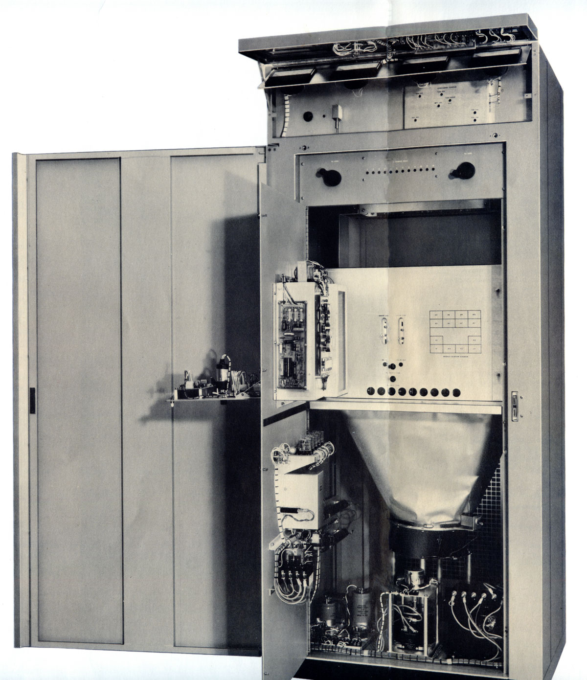
Original sales brochure for the MW1 (no A):

Harris MW1 sale brochure

Entire brochure is available here.

Harris MW1 interior view

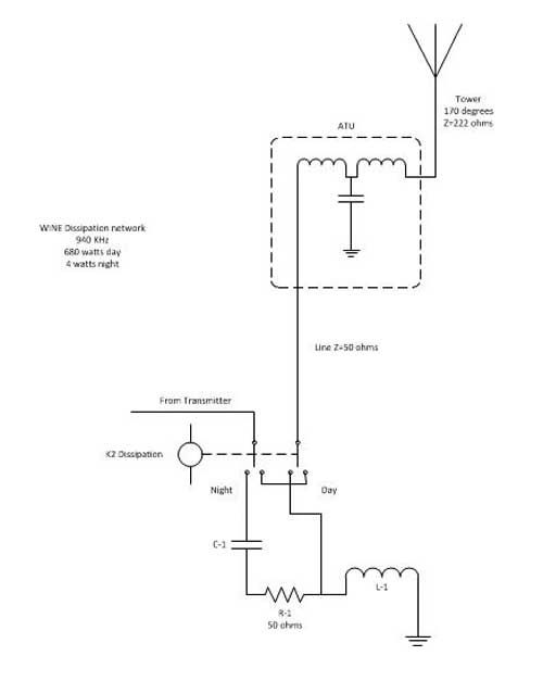
The other thing with this transmitter is it is very sensitive to any kind of VSWR.  Any change in the output impedance will quickly make itself apparent.  My Harrisburg MW1A had two ATU settings, one for winter and one for summer.  It was a slightly tall tower on 1230 KHz, thus any change in the ground system (e.g. snow cover) would upset the tower base impedance.

The other thing that goes bad is the large Rotron fan at the bottom of the cabinet.  They go bad about every 10-15 years or so.

The owner has spent some money on this particular unit, rebuilding and replacing several modules with new transistors, etc.  Will it last another thirty years?  Depends on if the RF and audio devices remain in production.

Update: WINE WRKI transmitter site move

I have been spending my days in Brookfield, Connecticut, dragging transmitters around and reconnecting them in various ways.  The WRKI-FM WINE-AM transmitter site is finally moving into the “new” transmitter building at the base of the tower.  Today, we moved WINE.

WINE was first signed on in 1963 on 940 KHz from a 170-degree non-directional tower on top of a pretty high hill.  That same tower serves as the antenna support for WRKI, which signed on in 1957.  The station runs 680 watts daytime, however since it is non-directional, it has some pretty serious power reductions at night.  The post-sunset power drops in two steps, 450 watts for the first hour, then 189 watts for the second hour, followed by 4 watts nighttime.

The 4-watt nighttime signal goes about 2-4 miles before it becomes unlistenable.  The Post Sun Set Authority (PSSA) allows the station to stay on the air with at least some coverage up to about 6:46 pm in the winter time and 10 pm in the summer, which is better than nothing.

The problem is, the Harris MW-1A transmitter goes down to 250 watts and no lower.  In order to make the nighttime power, the station switches to a dissipation network to burn off 246 watts of RF, at 50% percent AC-RF efficiency, which just ends up being a waste of power.  Further, the station engineers have been ignoring the PSSA because there are too many steps and it was easier to just switch to night power at sunset.

What we decided to do instead, was install a small low power night time transmitter, a Radio Systems TR-6000.  The MW1A can then be set to use the low power level for the first step of the PSSA, then switch the dissipation network in for the second step of the PSSA, and finally switch in the night transmitter at the proper time.

Harris MW1A AM transmitter, WINE 940 KHz, Brookfield, Ct

This is the Harris transmitter, new Circa 1981, which was cleaned up and moved into the new transmitter building.

WINE Parallel dissipation network and dummy load

The dissipation network.  This will have to be reconfigured for the proper power levels, once the night transmitter is installed.  The dissipation network is on the right, a dummy load is on the left.  The two large RF contactors switch the dissipation network in and out, or select which transmitter is feeding the antenna/dummy load.  This is the really, really old school way of doing it.  Most transmitters manufactured after 1990 or so can run at any power level, making a dissipation network unnecessary.

Before re-installing the dissipation network/dummy load, we lined the enclosure with copper mesh.  I don’t want that thing interfering with any of the other equipment nearby, which would be the STL receivers, satellite receivers, or Town of Brookfield police dispatch radios.

Schematically, it looks like this:

WINE 940 KHz Brookfield, CT night time dissipation network

This is the picture behind the transmitters, which shows the coaxial cable feed through ports and the dissipation network on the wall.

WINE WRKI transmitter room, behind the transmitters

It is a work in progress, so forgive the mess.

The CCA AM1000D

Still in use as the main transmitter after 42 years at WCKL 560 KHz, Catskill, NY.

CCA AM1000D transmitter, WCKL Catskill, NY

The last seven years or so, it has not had much use, the station being caught in some strange LMA with Clear Channel, then sold to the Black United Fund of NY something or another. They basically had it dark, turning it on for a few days each year to as not to lose their license.  Finally, they LMA’d it to Family Broadcasting (not to be confused with Family Radio).  There are rumors of a sale, but it remains to be seen.

They have been broadcasting an eclectic, free-form programming style which appears to be the work of mostly volunteers.

The station was first licensed in 1970, thus this is the original transmitter:

CCA AM 1000D name plate, WCKL Catskill, NY
CCA AM 1000D nameplate, WCKL Catskill, NY

Towers are 446 feet tall, which works out to 90 degrees at 560 KHz.

WCKL 560 KHz antenna array

The station is licensed to Catskill, but the transmitter site is located in Hudson, across the river. With the current ownership situation in flux, I would characterize the operation as “tenuous.”

The transmitter itself is a pretty simple high level modulation tube type transmitter.  It uses 4-400 tubes, like the RCA-BT1AR transmitters, and is built around a similar design, which makes sense as they were designed and built by former RCA engineers.  One of the CCA principles, Bernie Wise, still makes Energy Onix transmitters about 10 miles away in Valatie, NY.

Parts are fairly generic and still available.  Things like the modulation transformer may be harder to come by, however, Goodrich Electronics, Harbach Electronics, Energy Onix and others will be able to steer one in the right direction. I’d put up a schematic if I could find one.

I find these older tube-type transmitters often sing with modulation, especially the higher frequencies.  That sound and the soft sound of the blower moving air is the sound of radio, at least to me.

Implementing MCDL (Modulation Dependent Carrier Level)

Since the FCC waved some of its rules regarding carrier power and carrier shift on the AM broadcast band, AM stations are now able to implement MCDL or DCC (Dynamic Carrier Control) technology to save money on their electric bills.  This technology has the potential to save tens of thousands of dollars for higher-powered AM stations (high power=greater than 10 KW carrier level).

On a standard AM broadcasting station, the carrier represents two-thirds of the energy being transmitted, with the modulation index containing the other one-third.  The carrier contains no information; it is simply there on the center frequency at the power level authorized by the station’s license.  Thus, if the carrier can be reduced without affecting the quality of the broadcast reception, it will reduce to the overall power consumption of the transmitter.  In areas where electric costs are high, the savings can be substantial.

There are various ways to accomplish this.  The first is called Dynamic Carrier Control (DCC), where the carrier voltage is reduced during moderate modulation levels (between 20-50%) and restored during peaks.  This reduces the output power during average modulation, restoring most of it during quiet periods and peaks.  The next is Dynamic Amplitude Modulation (DAM), which is similar to DCC.  The most savings will be noted with less heavily processed programming such as talk radio because the higher the average modulation density is, the less the MDCL circuit reduces the carrier voltage level.  The little graph in the diagram shows the reduction in the carrier voltage vs. modulation levels.

Nautel DAM block diagram, courtesy of Nautel, Ltd.

Finally, Amplitude Modulation Companding (AMC) reduces the voltage in both the carrier and modulation product during peaks.  This results in better savings for higher-density modulation indexes.  It is also the most transparent of the three schemes, as the carrier is restored to full power during periods of low or no modulation levels. During peak modulation, the reduction does not drop the power level below the un-modulated carrier level.  The little graph in the diagram shows the reduction in the carrier voltage vs. modulation levels.

Nautel AMC block diagram, courtesy of Nautel, Ltd
Nautel AMC block diagram, courtesy of Nautel, Ltd   

Nautel has done extensive work on MDCL and includes several algorithms in their NX series transmitters.  For older Nautel transmitter models such as ND, XL, XR, and the J-1000, there is an outboard exciter, which is in a one-rack unit chassis.  Older transmitters may need a simple field modification to create a DC-coupled audio input.  The cost for the upgrade is approximately $5,000 USD, however, check with the regional Nautel sales rep.

Once the system has been installed, there are several things to be aware of:

  1. Modulation monitors may not work properly, especially older units, which will show significant carrier shifts and have carrier alarms.   Belar AMMA-2 modulation monitor is specifically built to work with MDCL transmitters.
  2. When making field strength readings, the MDCL circuitry must be turned off to get accurate readings.
  3. For stations running IBOC, the amount of carrier power reduction may need to be experimented with, as the effect of the carrier reduction may cause the transmitter to exceed the NRSC mask.

Currently, only Nautel and Harris are selling MDCL transmitters.  I spent several minutes poking around the Harris website and looking through their product brochures for the DX series transmitters and no mention of DCC o MDCL was found.  I’d be happy to include any information from Harris if it were made available.