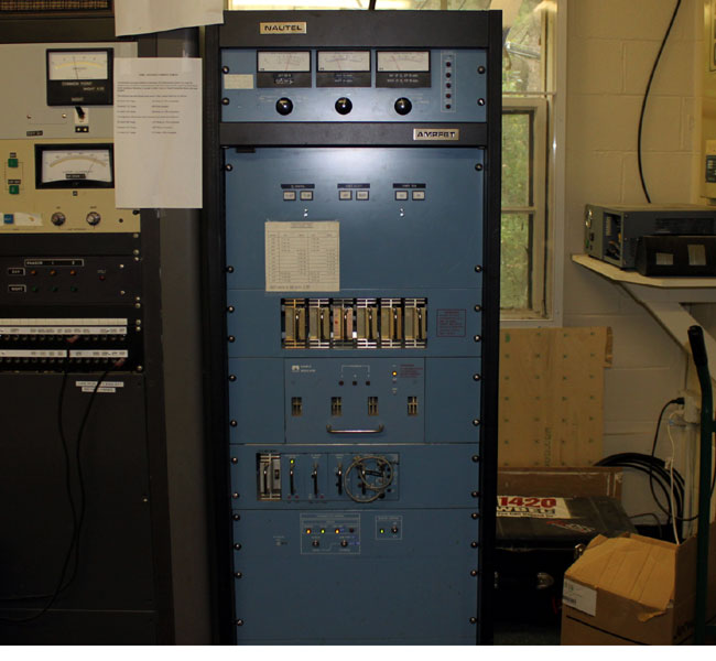
The Nautel AMPFET series transmitters date from the early ’80s through early ’90s. They were Nautel’s first attempt at MF Broadcast transmitters and were quite successful. This particular transmitter was installed in early 1990 at WBEC in Pittsfield, MA:
Nautel AMPFET 1 AM broadcast transmitter
I believe Nautel got started making MW transmitters for Marine Radio stations, Aeronautical and Marine radio beacons, and similar equipment. Their early equipment is very rugged and designed for rough/continuous service. The early solid-state broadcast transmitters like the AMPFET were not hot pluggable but who cares, they almost never break. The design is simple, and efficient and it sounds good on the air.
Early transmitters were housed in racks that were much shorter. In later versions, the racks became larger to standardize the transmitter size with comparable units of the day. Inside this cabinet, there is a lot of empty space.
The design is modular, RF modules and power supplies can be removed from the transmitter for repair, unlike the Harris AM transmitter products of the same or later periods.
There later AM transmitter versions built on the AMPFET experience.
Coming to an AM transmitter near you. The FCC announced that starting immediately, stations can employ Modulation Dependent Carrier Level or MDCL technology on AM transmitters. According to Public Notice DA 11-1535 (.pdf):
Use of MDCL technologies requires a waiver of Section 73.1560(a) of the Commission’s Rules, which sets upper and lower limits for an AM station’s operating power. We hereby establish procedures for AM broadcasters to seek a rule waiver in order to use energy-saving MDCL technologies.
Several transmitter manufacturers offer some version of MDCL in their newer models with the ability to update some older models. Harris Corporation offers something called “Amplitude Modulation Companding” (AMC) and “Adaptive Carrier Control” (ACC). While Nautel includes an option called “Dynamic Carrier Control” (DCC) on all NX series transmitters with the ability to upgrade some older transmitters. Continental offers Controlled Carrier Level Modulation (CCM) on later-model shortwave transmitters by installing SSM modulator, which can be retrofitted.
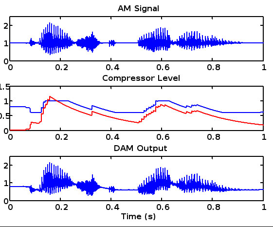
Nautel’s Dynamic Carrier Control (.ppt) (.pdf available here) reduces the carrier level during moderate modulation periods. The effect of this is to increase the perceived loudness at the receiver. During higher modulation periods, the carrier is increased to prevent distortion. The net effect is between 3 – 6 dB carrier reduction. During quite periods, the carrier is returned to full power to reduce noise.
Nautel Presentation on Dynamic AM carrier control
The potential savings are from 20-40%, which for a 10 or 50 KW station, would represent a significant reduction in the power bill. For a 50 kW station running an older transmitter, the savings would fall in the $37,000 to $56,000 per year range. In some cases, smaller stations may be able to get rid of a demand meter, which would also represent significant savings. The threshold for demand meters around here is 5,000 KWh per month.
The FCC further notes that:
The reduction in AM signal power at certain modulation levels inevitably exacts some penalty upon audio quality. Depending on the content of the audio program, MDCL algorithms may introduce some audio distortion or may decrease the signal-to-noise ratio in the receiver. In addition, MDCL algorithms may erode coverage slightly at the fringes of the AM station’s protected service area. Both the long experience of transmitter manufacturers and broadcasters abroad, and the initial reports from experimental operations in Alaska however, indicate that such adverse effects are generally imperceptible.
This would be especially true for higher-powered stations that stand to save the most money.
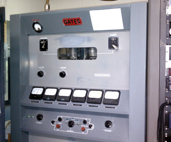
This transmitter is found at WBEC in Pittsfield, MA. It is still in operation as a standby transmitter for that station and has a manufacture date of 1955. The Broadcasting Yearbook places WBEC first on air in March of 1947. This would be the second transmitter the station installed.
Gates BC1J in service as a backup at WBEC, September 2011
The transmitter has been in service for 56 years, which is remarkable. This was made back when Gates was just Gates (no Harris) and AM radio was still king of the airwaves. TV was coming of age, FM radio still had a ways to go until widespread acceptance by the general public.
This transmitter doesn’t get to run very much, the third transmitter installed at WBEC is a Nautel AMPHET-1.
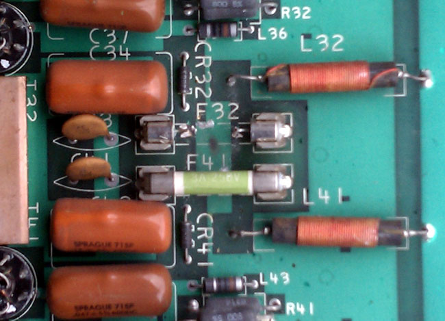
The case of the blown fuse, or rather the blown up fuse:
Blown 10 amp fuse on Harris SX5 PA board
F32 is blown into small bits and had to be vacuumed out of the bottom of the transmitter. The reason why is the pair of MOSFETs connected to that circuit were shorted. Of course, the reason for the shorting of MOSFETs needed to be investigated. What I found was on the underside of the PA board where the brass stand-off attacked the toroid combiner board, the nuts attaching the stand-off to the combiner board were loose and there was a big arc mark.
I tightened everything up and replaced the MOSFETS, marking them with a pen in case they short again, in which case the drive section needs to be closely examined.